

0 引言
机械蒸汽再压缩(mechanical vapor recompression, MVR)系统在电/蒸汽价格比合适的情况下,经压缩机压缩二次蒸汽增焓增压后用于加热物料,充分利用了原先浪费的二次蒸汽潜热,具有传热温差小、蒸发过程温和、物料产品在蒸发器中停留时间短、操作简单、可根据工况条件调节负荷、操作成本低、可实现自动化运行等特点,广泛应用于海水淡化、化工、食品和工业废水处理等领域[1,2,3,4,5]。蒸发器作为MVR系统的核心设备,其传热性能对整套机组运行能耗影响极大,小温差换热的特点客观上对换热器的传热效率提出了更高的要求[6],而当前传统光滑圆管折流板蒸发器存在效率低、体积大、造价高等问题,开发更高效的蒸发器有利于降低MVR系统的投资和运行费用。
蒸发器一般由加热室与蒸发室两大部分组成。而换热器则构成了加热室的核心,其主要作用是将管外侧二次蒸汽的凝结热传递给管内溶液,促使溶液进入蒸发室沸腾汽化。强制循环蒸发器和降膜式蒸发器是MVR系统最常采用的两种蒸发器形式。三维变形管换热器是一种新型纵向纯逆流换热器,采用三维变形管作为换热元件,壳程不设折流板,通过捆扎即可实现管束自支撑,且双侧螺旋流实现强化换热,既可以降低壳侧阻力,又提高了管侧湍流度,运行可靠无振动,在列管式换热器领域得到广泛关注[7]。孟继安等[8]、CHENG等[9]、WU等[10]和GHAZANFARI等[11]采用理论分析与数值模拟的方法对三维变形管管内层流换热与流动特性进行了研究,结果表明三维变形管可较大程度地强化边界层换热,而流阻增加较小。DZYUBENKO等[12,13]对三维变形管管侧和壳侧传热传质与流阻性能展开了研究,并拟合出关联式。GU等[14]采用重整化群(renormalization group, RNG)k-ε模型对具有新型耦合涡流棋盘管布置的三维变形管换热器进行了模拟,对比了长短轴比(A/B)和螺距S对二次流、努塞尔数Nu和摩擦系数 f 的影响,并采用综合评价指数Nu∙f -1/3进行了评估,发现所有三维变形管方案的Nu、f 和Nu∙f -1/3均明显高于光滑圆管方案。YAN等[15]在将三维变形管用于强化高黏度流体环氧树脂的传热研究中也取得了令人满意的结果。YANG等[16]、TAN等[17]和朱冬生等[18]对三维变形管管内湍流换热过程进行了实验和数值研究,并采用场协同理论分析了管内强化传热机理,获得准则关联式。BARRAZA-COLÓN等[19]提出利用三维变形管强化换热和热回收效率高的特点来改进余热回收技术,讨论了在高黏度流体热回收场合的应用,结果表明,与传统的管壳式换热器相比,三维变形管换热器的表面积减少了高达45%,压降减少了15%。SHAHSAVAR等[20]采用三维数值模拟了变螺距对三维变形管内的非牛顿CMC/CuO纳米流体热力性能和熵产的影响,并对比了不同纳米颗粒浓度和雷诺数的情形,通过对比分析,获得了三维变形管中纳米流体与光滑管中纳米流体流量的热熵和摩擦熵最低比率。在三维变形管抗结垢性能方面,卿德藩等[21]对扭曲椭圆管用于套管式管外蒸汽冷凝换热器的传热、流阻与结垢特性进行了理论与实验研究,并与直圆管、三维低肋管进行了对比。DANIELSEN[22]对三维变形管壳管式换热器的传热性能、流阻性能、抗结垢特性和防振动特性进行了较为全面的调研和分析。在三维变形管用于冷凝换热方面,ZHANG等[23]对不同结构参数的三维变形管的冷凝传热特性进行实验研究,结果表明冷凝传热系数随着换热管壁面凝结水过冷度的增加而减小,而每根管道的增强因子几乎不变;三维变形管冷凝传热系数随着椭圆度的增加而增加,最高增加约34%。GU等[24]以煤油混合物为冷凝蒸汽,以空气为不凝气体,对光滑管及三维变形管进行对比实验研究,结果表明,与普通圆管相比,三维变形管的传热系数可提高1.5 ~ 3倍;由于质量扩散阻力的增加和汽-液界面处的蒸汽冷凝温度的降低,不凝性气体的存在会显著降低冷凝传热性能;利用传热传质类比法,根据实验数据建立了混合气凝结换热系数的关联式。此外,在实验与数值模拟方面,ZHAI等[25]考察了纳米流体在三维变形管中的流动和传热特性,研究了螺旋扭矩、螺旋角和纳米颗粒分散度对三维变形管中的流体流动和传热的影响。LI等[26]采用实验与数值模拟方法研究了错流布置的三维变形管束的空气侧传热和压降特性,并获得了准则关联式。莫逊等[27]基于安东旭[28]得出的三维变形管管内降膜蒸发关联式和管外蒸汽冷凝计算流体力学(computational fluid dynamics, CFD)数值模拟,分析发现采用三维变形管降膜蒸发器的管侧与壳侧的传热膜系数在不同关键参数影响下优于直圆管的现象。刘世杰等[6]以水介质考察了三维管蒸发器应用于较大雷诺数Re时的换热性能,在13 000 < Re < 110 000范围内,研究了三维变形管的不同结构参数对管内传热与压降性能的影响。
1 纤维素生产末端废水零排放项目MVR蒸发器设计
1.1 工程应用案例设计条件
某纤维素生产企业的废水零排放项目,年产10 000 t纤维素醚,生产末端工业高浓度盐废水采用“超频震动薄膜过滤 + MVR浓缩”工艺。MVR浓缩设计处理能力为400 m3/d,副产工业盐,冷凝水和其他废水进入MVR冷凝水生化处理设备。项目于2019年底调试完成并投入使用。末端废水经过前处理后,进入MVR浓缩系统时,氯化钠质量浓度为12% ~ 18%,有少量丙二醇及聚丙醚,化学需氧量(chemical oxygen demand, COD)为 4% ~ 6%(质量溶度)。
1.2 设计流程与管内外传热、流阻计算
三维变形管(后面简称3D管)换热器的设计流程图如图1所示。

Fig. 1 Design and calculation flow chart of three-dimensional deformation tube MVR evaporator图1 三维变形管MVR蒸发器设计计算流程图 |
其中3D管蒸发器管内流体的Nu与f 的计算采用文献[6]中基于MVR废水浓缩应用场合拟合的公式:
$Nu=1.023\times R{{e}^{0.432}}\times P{{r}^{0.33}}\times {{\left( \frac{A}{B} \right)}^{0.131}}\times {{\left( \frac{S}{{{d}_{\text{e}}}} \right)}^{-0.1778}}$ (1)
$f=15.292\times R{{e}^{-0.471}}\times {{\left( \frac{A}{B} \right)}^{0.471}}\times {{\left( \frac{S}{{{d}_{\text{e}}}} \right)}^{-0.409}}$ (2)
式中:de为3D管的管外侧水力直径。
1.3 管内换热盐水浓度的影响修正
由于3D管蒸发器管内流体的Nu与f的计算公式(1)和公式(2)是在盐水质量浓度为10%的情形下得出的,考虑到不同的MVR蒸发浓缩场合中盐水浓度的差异对流体物性的影响,为了提高计算模型的精度,并针对本项目以NaCl盐为主的特点,采用数值模拟的方式对盐水质量浓度的影响进行了分析,并拟合出盐水浓度影响修正关系式。
以质量浓度变化范围为4% ~ 16%的盐水为流动介质进行传热性能与流阻性能的模拟研究,利用SolidWorks软件进行三维立体空间的建模,并且建立了相应的圆管模型。换热管的长度均为1 200 mm,采用圆管的直径为ϕ 25 mm;3D管模型中螺距S为300 mm,长短轴比(即A/B)为1.61。采用ICEM软件进行网格划分,选用精度较高的六面体结构化网格,3D管的局部网格示意图如图2所示。为保证对壁面附近边界层的准确捕捉,对近壁面流体流动区域进行加密,以保证计算结果的精度。

Fig. 2 Local grid diagram of 3D-deformation tube: (a) cross-section grid; (b) vertical grid图2 3D管局部网格示意图:(a)横截面网格;(b)纵向网格 |
${{h}_{\text{n}1}}={{h}_{\text{n}}}\times {{\text{e}}^{-0.024x}}\ \left( {{R}^{2}}=0.9981 \right)$ (3)

Fig. 3 Variation of heat transfer coefficient inside the tube with brine concentration图3 管内传热系数随盐水浓度变化图 |
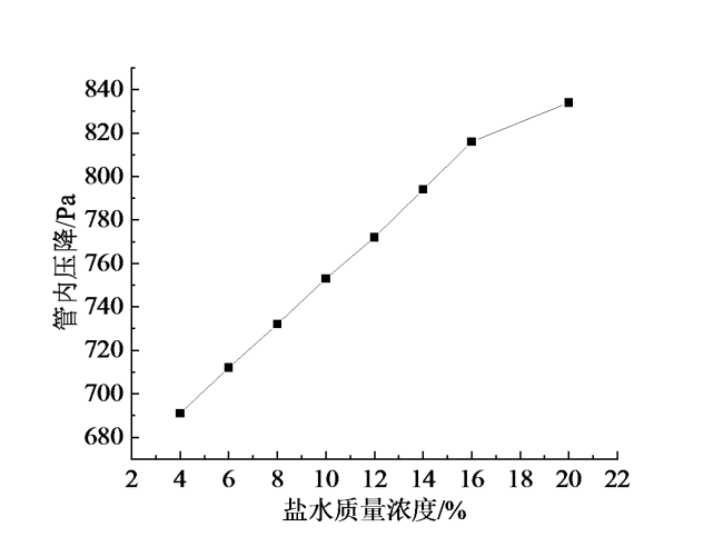
Fig. 4 Variation of fluid pressure drop with brine concentration图4 流体压降随盐水浓度变化图 |
式中:hn和hn1分别为清水的管内传热系数和盐水的管内传热系数;x为盐水质量浓度。
由图4可知,随着盐水浓度的增加,流体的压降逐渐上升,说明盐水浓度的增加会导致设备能耗的升高。盐水质量浓度从4%增大到16%时,流体的压降从691 Pa升高至834 Pa,增加了20.7%,两者呈现近线型正相关。
得到盐水浓度对管内压降的影响修正公式:
$\Delta {{P}_{n1}}=\Delta {{P}_{n}}\times {{\text{e}}^{0.0275x}}\ \ \left( {{R}^{2}}=0.9996 \right)$ (4)
式中:ΔPn和ΔPn1分别为清水管内压降和盐水的管内压降。
1.4 设计计算结果与传统直圆管蒸发器的对比
表1给出了3D管蒸发器优化设计结果与传统直圆管蒸发器设计参数的对比。从设计参数对比可知,采用3D管替代直圆管后,计算总传热系数提高了41.93%,换热面积减少了29.05%,蒸发式换热器高度降低了2 m,筒体直径由2.1 m变成1.9 m,总体积降低了31.78%,同时管内计算压降提高了12.41%,但仍在允许压降范围内。
Table 1 Comparison of optimized design parameters of 3D tube evaporator and traditional straight circular evaporator design parameters表1 3D管蒸发器优化设计参数与传统直圆管蒸发器设计参数对比 |
| 参数 | 直圆管蒸发器 | 3D管蒸发器 | 对比 |
|---|---|---|---|
| 废水循环流量/(m3/h) | 3 850 | 3 850 | |
| 废水处理量/(m3/h) | 17.36 | 17.36 | |
| 废水进口温度/℃ | 98.05 | 98.05 | |
| 废水出口温度/℃ | 99.8 | 99.8 | |
| 管内压力/kPa | 150(表压) | 150(表压) | |
| 管内允许压降/kPa | 35 | 35 | |
| 管内压降/kPa | 27.4 | 30.8 | +12.41% |
| 蒸汽流量/(t/h) | 14.35 | 14.35 | |
| 蒸汽温度/℃ | 110 | 110 | |
| 壳程压力/kPa | 143(绝对) | 143(绝对) | |
| 总换热量/kW | 8 889.1 | 8 889.1 | |
| 换热面积/m2 | 1 252.62 | 888.69 | -29.05% |
| 总传热系数/[W/(m2∙K)] | 837 | 1 188 | +41.93% |
| 裕量/% | 30.6% | 21.1% | |
| 流程 | 1/1 | 1/1 | |
| 换热管尺寸/mm | Φ 32 × 1.5 × 10 000 | Φ 32 × 1.5 × 8 000 A = 38,B = 22, P = 300 | |
| 筒体尺寸/mm | Φ 2 100 × 12 000 | Φ 1 900 × 10 000 | -31.78% |
| 换热管数目/根 | 1 246 | 1 105 | |
| 换热管材质 | 钛 | 钛 | |
| 筒体材质 | 304不锈钢 | 304不锈钢 |
2 实际运行结果与分析
项目于2019年11月正式投运,收集了2019年11月14日至16日连续3天和2021年8月23日至26日连续4天共14个工况点的现场运行数据。考察期内,设备每天仅运行2班次16 h(即每天连续运行16 h),取每个班次8 h的运行数据平均值作为一个运行工况点。MVR运行压缩机功率(取每个工况点的平均功率)随进料量和蒸发量的变化情况见图5;对现场分散控制系统(distributed control system, DCS)的实际运行监测数据进行了分析整理(由于现场对系统阻力的测试传感器数据不全,仅能做综合换热能力的校核,不能做换热器流阻校核),得到各工况点均值的运行数据与设计值对比,如表2所示。
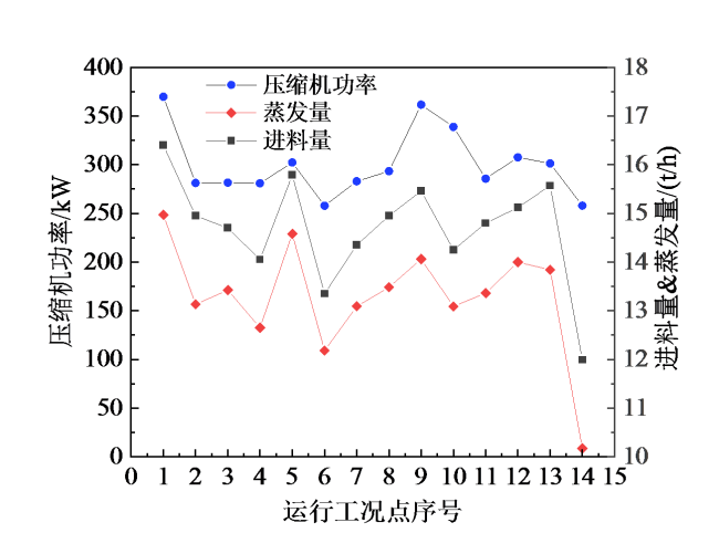
Fig. 5 Schematic diagram of the change of MVR compressor power with feed volume and evaporation volume during actual operation图5 实际运行时压缩机功率随进料量和蒸发量的变化示意图 |
Table 2 Comparison of comprehensive heat transfer performance and design conditions of actual operation of 3D tube MVR evaporator表2 3D管MVR蒸发器实际运行综合换热性能与设计工况对比 |
| 参数 | 设计值 | 实际监测值 | 对比 |
|---|---|---|---|
| 废水循环流量/(m3/h) | 3 850 | 3 997 | +3.80% |
| 新进废水量(常温)/(m3/h) | 17.36 | 14.95 | -13.90% |
| 循环倍率 | 221.8 | 267.4 | +20.60% |
| 废水进口温度/℃ | 98.05 | 96.53 | |
| 废水出口温度/℃ | 99.8 | 98.39 | |
| 压缩机进口压力/kPa | 81.31 | 60.94 | |
| 压缩机出口压力/kPa | 133.45 | 105.35 | |
| 压缩比 | 1.641 | 1.729 | |
| 压缩机耗电功率/kW | 465.21 | 300.21 | -35.47% |
| 循环水泵耗电功率/kW | 113.9 | 93.96 | -17.51% |
| MVR系统总耗电功率/kW | 706.23 | 521.29 | -26.19% |
| 蒸汽流量/(t/h) | 14.35 | 13.22 | -7.90% |
| 蒸汽温度/℃ | 110 | 103.14 | |
| 换热温差/℃ | 11.08 | 5.63 | -49.20% |
| 出料量/(m3/h) | 3.01 | 1.98 | -34.20% |
| 总换热量/kW | 10 753.5 | 8 265.1 | -23.10% |
| 总传热系数/[W/(m2∙K)] | 1 188 | 1 586 | +33.50% |
| 系统能效 | 15.23① | 15.86 | +4.13% |
①设计系统能效为设计工况条件下的预测值。 |
从图5的实际运行情况可知,压缩机功率与蒸发量基本呈现相似变化趋势;而由于不同工况进料的含盐浓度有差异,导致蒸发量与进料量的比值出现波动,进而影响到压缩机功率的变化幅度,吨水处理压缩机耗电量在18.81 ~ 23.78 kW∙h之间波动。对比表2的实际运行综合换热性能与设计工况可知,处理废水负荷率仅为86.1%,从出料情况看,出料量为设计值的65.45%,表明进料废水含固率低于设计值;由于实际运行处理量比设计值低,蒸发负荷在63% ~ 108%之间波动,实际采用的平均循环倍率高于设计值20.6%,实际运行换热温差仅为设计值的50.8%,换热系数比设计值高33.5%,远高于传统直圆管MVR蒸发器的综合换热系数(700 ~ 1 000 W/(m2∙K)),表明换热器的实际换热能力高于设计运行要求;尽管传热系数高于设计值,但系统实际能效水平与设计值相比只提高了4.13%,主要是由于为了降低蒸发器结垢风险,实际运行维持了较高的循环倍率,以确保管内维持较高的流速,因此循环泵功率不如负荷率降低明显,在一定程度上抵消了压缩机功耗降低的影响;但实际运行和设计计算工况系统能效均明显高于采用传统直圆管MVR蒸发系统设计工况系统能效值(项目采用传统直圆管蒸发器的MVR蒸发系统方案设计预测系统能效为13.74),表明优良的换热性能有利于降低MVR系统能耗(能效水平提高了约15%)。需要特别说明的是,蒸发器壳侧饱和蒸汽温度采用了现场监测系统的实测值,由于压缩机出口蒸汽存在过热现象,系统设置了喷水减温装置,确保进入蒸发器的蒸汽接近饱和状态。
鉴于项目实际运行工况负荷率与设计工况存在较大的偏差,根据现场运行数据进一步考察负荷率对蒸发器能效水平的影响,如图6所示。从实际运行MVR系统能效随蒸发负荷的变化趋势可以看出,在设计负荷附近,MVR系统能效处于高值,最高超过了17,且在负荷率为90%以上时系统能效均在16以上;而当负荷率降至70%左右时,系统能效降至14左右,即相对于设计蒸发负荷附近的系统能效,系统能效降低了约18%。主要原因是在该项目的测试负荷变化范围内,系统运行时虽然蒸发量降低,但为了降低管内壁结垢风险,循环水泵仍基本维持在接近设计循环量甚至略高于设计循环量的高负荷运转(主要是系统阻力低于设计值,在不降低变频器频率的情况下,循环量会高于设计值),因此循环泵的运行功率与设计工况相比差异不大,而其他如真空泵和物料输送泵等辅助用电设备运行动力消耗也不如负荷率下降那么明显。但即使负荷率低至70%时,系统能效水平仍然远高于直圆管蒸发器额定负荷系统能效水平。而当负荷率升至设计额定负荷的水平时,系统能效将达到16.7左右,为设计预估值的109.7%,表明实际运行系统能效高于预估值,更优于传统直圆管MVR蒸发式系统(提高了21.5%)。
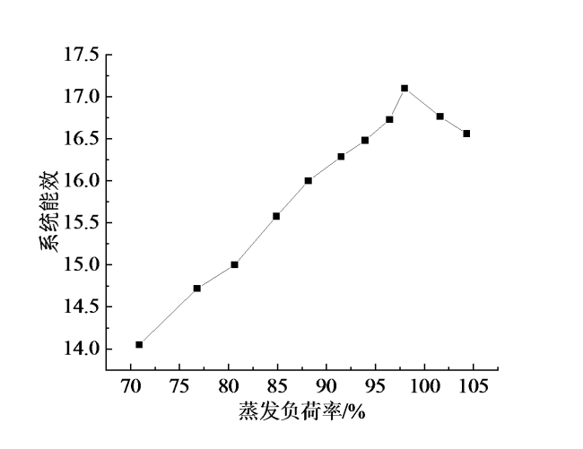
Fig. 6 The trend of MVR system energy efficiency with evaporation load in actual operation图6 实际运行时MVR系统能效随蒸发负荷率的变化趋势 |
3 结论
对采用三维变形管的MVR蒸发浓缩技术用于某纤维素生产企业的废水零排放项目的实际运行效果进行了分析,得到以下结论:
(1)相比于采用光滑圆管,采用三维变形管的MVR蒸发器具有优异的强化传热性能,在减少了29.05%换热面积的情形下,其实际运行效果仍优于设计预期值,可满足用户使用要求,表明采用该强化换热技术的MVR蒸发器节材节能效果明显。
(2)在实际运行工况条件下,三维变形管MVR蒸发器的综合换热系数达到1 586 W/(m2∙K),高于设计值33.5%,分析导致这种提升的主要原因,一是测试期间管内污垢程度低于设计预期值(考察测试前两周正好进行了设备例行维护清洗);二是物料中少量固形物的存在有助于管内流体的扰动,一定程度上对管内换热能力起到了提升作用;三是实际维持了较高的循环倍率,设备运行时管内介质流速略高于设计值。
(3)负荷降低对系统能效有明显影响,当蒸发负荷率降至70%时,整个MVR系统能效较额定负荷下降了18%左右,但由于三维变形管蒸发器的优异换热性能,系统能效仍处于较高水平,表明基于三维变形管的MVR蒸发系统具有较好的部分负荷适应性。为了使蒸发器换热管内物料流速维持较高水平,在实际运行蒸发负荷降低时采用了更高的循环倍率,因此整个测试期间系统能效与设计额定工况能效值相比平均仅提升了4.13%,在整个测试观察期内,各工况点蒸发器的平均蒸发量为设计值的70.87% ~ 104.32%,系统能效在14.05 ~ 17.10,且在接近设计蒸发量的工况条件下,系统能效维持在16.3以上。
