扰流空心翅片式微流道液冷板流动换热特性研究
[周蔚南1, 2, 3 , 孙钦1, 3 , 关胜利4 , 汪广武4 , 孙晨明4 , 吴伟5 , 董凯军1, 3, †  ]
]
]
|
|


作者简介:周蔚南(1998-),女,硕士研究生,主要从事数据中心节能技术研究。董凯军(1971-),男,博士,正高级工程师,主要从事数据中心冷却节能与蓄能技术、工业节能技术、能源管理与高效利用技术研究。
液冷板冷却技术是解决高功率芯片热管理问题最有前途的技术之一,带翅片结构的液冷板具有低流阻、低热阻的优势,因而受到广泛关注。目前翅片结构多以实心为主,空心交错翅片对液冷板散热能力和压降等冷却特性的影响尚未得到系统的研究。对此,设计了空心交错翅片液冷板,采用数值模拟的方法研究进口温度和流量对液冷板流动换热特性的影响。模拟结果表明,空心翅片式液冷板具有良好的散热性能,随着进口温度的升高,液冷板温度不均匀性逐渐降低,但降低趋势有所减缓,而流量的增大对降低平均热阻有显著的作用,当进口流量超过1.2 L/min时,液冷板的平均热阻可低于0.04℃/W;然而,流量的增大也提高了流动阻力,当流量增大至1.7 L/min时,流体出口区域形成涡旋,产生回流区,不利于液冷板的散热效果,且流动阻力增大。
The liquid cooling plate technology is one of the most promising technologies to solve the thermal management problems of high-power chips. The liquid cooling plate with fins has the advantages of low flow resistance and low thermal resistance, and thus has received wide attention. However, the fins applied to the liquid cooling plate are mostly solid, and the influence of hollow staggered fins on the heat dissipation capacity and pressure drop characteristics has not been systematically studied. In this paper, hollow staggered fins were designed and numerical simulations were used to study the effects of inlet temperature and flow rate on the flow heat transfer characteristics of the liquid cooling plate. The simulation results showed that the hollow staggered fin liquid cooling plate had good heat dissipation performance. And the temperature un-uniformity decreased gradually with the increase of inlet temperature, while the decreasing trend slowed down. The increase of flow rate had a significant effect on reducing the average thermal resistance. When the inlet flow rate exceeded 1.2 L/min, the average thermal resistance of the liquid cooling plate was lower than 0.04°C/W. However, the flow resistance also increased with the increase of flow rate. When the flow rate was up to 1.7 L/min, the vortex was formed in the fluid outlet area and the reflux zone was generated, which was not conducive to the cooling effect of the liquid cooling plate, and the flow resistance increased.
随着计算机技术的发展, 芯片运行功率显著提升, 同时, 加工和封装技术的优化使芯片的物理尺寸不断缩小, 进而使其功率密度越来越大, 并且该增长趋势越来越快[1, 2]。在这一背景下, 芯片的热管理问题日益凸显, 受到了全球学者的广泛重视[3, 4]。目前, 空气冷却是最成熟的冷却技术, 但空气密度小、排热能力较差, 其最大散热能力约为37 W/cm2[5], 难以应对超过100 W/cm2的高热流密度。因此, 热管、热电冷却器和液冷板等用于高功率芯片热管理的冷却技术被开发出来[6]。其中热管、热电冷却器结构较为复杂, 不易加工, 工作不稳定, 导致目前的应用普及度较低。而液冷板技术具有散热能力强、安装方便、工作运行稳定的优点, 成为解决芯片热管理问题最有前途的技术之一[7]。
液冷板的结构直接影响其换热能力和流动阻力, 结构优化[8, 9, 10]成为近年来液冷板相关研究工作的重点之一。为了降低热阻, 研究者们提出了带翅片结构的高效散热液冷板[11, 12, 13, 14], 该结构导热系数高, 压降低, 冷却系统运行能耗减少[15, 16]。翅片的形状对液冷板性能的影响得到了广泛的研究, NDAO等[17]对不同的翅片截面形状和传热系数间的关系进行了探究; 对于斜翅片, YONG等[12]研究了其角度及间距对微通道热沉的影响, 结果表明, 当雷诺数Re= 690时, 斜翅片微通道液冷板的热阻可达到0.089℃/W, 实现了液冷板热阻低于0.1℃/W的目标。翅片高度是影响液冷板性能的另一重要因素, 翅片高度关系到液冷板对流换热表面积以及整体的流动阻力, PRAJAPATI[18]发现翅片顶部开放空间产生的净对流表面积和典型流动行为是影响液冷板整体热性能的主要原因; 增大翅片高度能够提高液冷板的对流换热面积, 同时也会增大流动阻力, BHANDARI等[19]的研究表明, 1.5 mm高度的翅片(流道高度2 mm)为最佳值, 能够实现更好地传热且液冷板的流动阻力在可接受范围内。而对于翅片的排布方式, CHIU等[14]研究了不同密度的交错布置的微翅片对液冷板传热特性的影响, 结果表明液冷板的传热性能取决于翅片阵列的密度以及截面面积的大小。此外, 进出口方式对液冷板内流量分配特性影响很大。刘东等[20]研究了6种进出口方式, 提出以流量和换热不均匀系数来评价进出口方式的影响。YADAV等[21]针对入口/出口分歧管相互连接的微通道之间的流量不均匀性, 提出了一种改善流动分布不均的新技术。可见, 合理的进口方式有助于提高液冷板温度均匀性。
综上所述, 目前研究人员对实心翅片的形状、角度、高度和排布方式对液冷板流动换热效果的影响已开展了较为深入的研究, 而对于空心交错翅片尚未见到系统的报道。相较于实心翅片, 空心翅片的结构进一步增大了翅片与冷却剂间的接触面积, 从而更有利于强化换热。对此, 本文设计扰流空心翅片式微流道液冷板, 并通过三维数值方法模拟空心交错翅片液冷板内的流量分配和换热特性, 通过温度不均匀系数、平均热阻和平均传热系数评价液冷板的散热能力, 为液冷板的设计优化提供新思路。
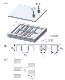
扰流空心翅片式微流道液冷板的结构如图1所示, 长方体空心翅片在液冷板内交错分布; 进出口位于液冷板的同一侧, 使得冷却剂的流线在有限的空间内增长, 且同侧进出口便于实际应用的安装。液冷板的长、宽、高分别为62 mm、60 mm、10 mm, 在液冷板底部中心位置设置尺寸为45 mm × 45 mm × 3 mm的芯片发热源, 芯片的发热量设置为300 W, 液冷板内部结构的几何参数如表1所示。
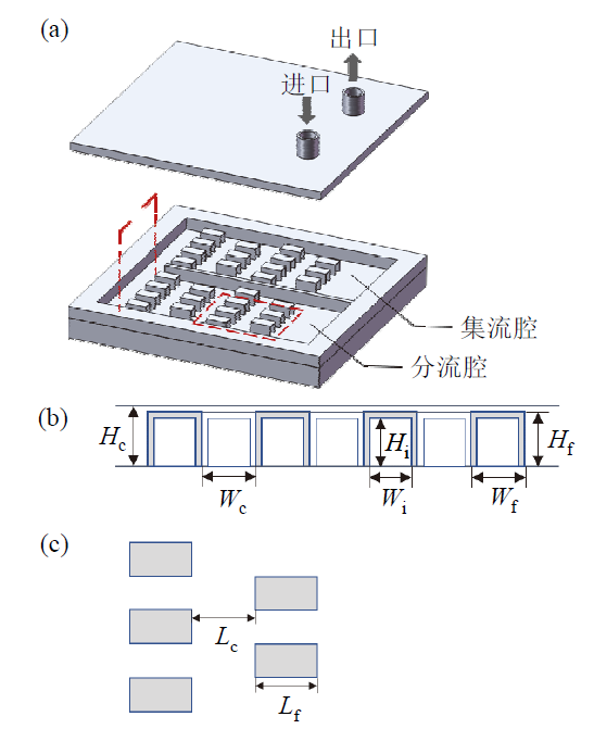 | 图1 (a)扰流空心翅片式微流道液冷板结构图; (b)空心交错翅片局部截面图; (c)空心交错翅片布置图Fig. 1 (a) Schematic diagram of liquid cooling plate with hollow-fin; (b) sectional diagram of hollow staggered fins; (c) hollow staggered fin layout |
| 表1 扰流空心翅片式微流道液冷板结构参数 Table 1 Structure parameters of liquid cooling plate with hollow-fin |
采用ANSYS 18.0软件建立三维立体模型, 对流体在整个液冷板内的流动及传热进行数值模拟, 并做出如下假设[22]:①流体为不可压缩流体, 流体和固体的热力学参数为定值; ②忽略中央处理器 (central processing unit, CPU)与液冷板之间的接触热阻; ③忽略热辐射的影响; ④流道表面光滑; ⑤液冷板的出口压力为大气压力。具体的控制方程如下。
液冷板的固体区域能量方程:
${{k}_{\text{s}}}{{\nabla }^{2}}{{T}_{\text{s}}}=0$ (1)
液冷板的流体区域能量方程:
$\rho {{c}_{p}}\left( V\nabla T \right)={{k}_{\text{f}}}{{\nabla }^{2}}T$ (2)
式中:$\rho$为密度; V为流速; ks为固体导热系数; kf为流体导热系数; cp为流体定压比热; Ts为固体的温度; T为流体温度。
连续性方程:
$\nabla \cdot V=0$ (3)
动量方程:
$\rho \left( V\cdot \nabla V \right)=-\nabla p+\mu {{\nabla }^{2}}V$ (4)
由于本文讨论的空心翅片式微流道液冷板内有较多扰流结构, 且流体属于低雷诺数流动, 因此选择重整化群(renormalization group, RNG)k-ε 模型, 其湍流动能方程为:
$\begin{align} & \frac{\partial }{\partial t}\left( \rho k \right)+\frac{\partial }{\partial {{x}_{i}}}\left( \rho k{{u}_{i}} \right)=\frac{\partial }{\partial {{x}_{j}}}\left( {{\alpha }_{k}}{{\mu }_{eff}}\frac{\partial k}{\partial {{x}_{j}}} \right)+ \\ & {{G}_{k}}+{{G}_{b}}-\rho \varepsilon \end{align}$ (5)
扩散方程:
$\begin{align} & \frac{\partial }{\partial t}\left( \rho \varepsilon \right)+\frac{\partial }{\partial {{x}_{i}}}\left( \rho \varepsilon {{u}_{i}} \right)=\frac{\partial }{\partial {{x}_{j}}}\left( {{\alpha }_{\varepsilon }}{{\mu }_{eff}}\frac{\partial \varepsilon }{\partial {{x}_{j}}} \right)+ \\ & {{C}_{1\varepsilon }}\frac{\varepsilon }{k}\left( {{G}_{k}}+{{C}_{3\varepsilon }}{{G}_{b}} \right)-{{C}_{2\varepsilon }}\rho \frac{{{\varepsilon }^{2}}}{k} \end{align}$(6)
式中:k为湍流动能; ε 为湍流动能耗散率; t为时间; ${{u}_{i}}$为流体在i方向上的速度分量; ${{\mu }_{eff}}=\mu +{{\mu }_{t}}$, $\mu $为流体的动力黏度, ${{\mu }_{t}}$为湍流黏性系数, ${{\mu }_{t}}=\rho {{C}_{\mu }}{{{k}^{2}}}/{\varepsilon }\; $; ${{C}_{\mu }}$、${{C}_{1\varepsilon }}$、${{C}_{2\varepsilon }}$、${{C}_{3\varepsilon }}$为模型常数; ${{G}_{k}}$为由于平均速度梯度而产生的湍流动能; ${{G}_{b}}$为由于浮力产生的湍流动能, 对于不可压缩流体, ${{G}_{b}}$= 0; ${{\alpha }_{k}}$和${{\alpha }_{\varepsilon }}$分别为对于$k$和$\varepsilon $的湍流普朗特数。
计算时取液冷板的进口为速度进口, 出口为压力出口, 并且采用流固耦合边界条件。
为了评价液冷板的散热性能, 数值模拟区域的温度不均匀系数θ 定义为:
$\theta =\frac{{{T}_{cpu, max}}-{{T}_{cpu, min}}}{{{T}_{cpu, ave}}}$ (7)
式中:${{T}_{cpu, max}}$、${{T}_{cpu, min}}$和${{T}_{cpu, ave}}$分别为CPU的最高温度、最低温度和平均温度; θ 的值越小, 说明温度不均匀性越小。
液冷板的平均热阻(℃/W)可定义为:
${{R}_{th, ave}}=\frac{{{T}_{cpu, ave}}-{{T}_{in}}}{Q}$ (8)
式中:${{T}_{in}}$为冷却剂的进口温度; Q为发热量。
液冷板的平均传热系数定义为:
${{h}_{ave}}=\frac{Q}{A\left( {{T}_{cpu, ave}}-{{T}_{f, ave}} \right)}$ (9)
式中:${{T}_{f, ave}}$为流体的平均温度。
采用去离子水为流体工质, 流体和固体接触面无滑移。3 mm厚的硅基材料为发热源, 发热量为300 W, 液冷板材料为铜, 流体与固体的具体参数详见表2。
| 表2 材料热物性参数 Table 2 Thermophysical properties of materials |
为探究扰流空心翅片式微流道液冷板流动换热特性, 寻找合适的液冷板的进口流量和温度来实现良好的散热能力以及合理的流动阻力, 本文采用正交法对不同进口流量和温度进行正交模拟, 进口流量Qv分别设置为0.5 L/min、0.7 L/min、1.0 L/min、1.2 L/min、1.5 L/min; 进口温度Tin分别设置为25℃、28℃、31℃、34℃、37℃、40℃; 共30组数值模拟对照组。
在进行研究之前, 对网格独立性进行了详细分析, 以消除因网格粗糙而产生的误差。表3显示了三个网格系统的概要, 采用四面体单元的非结构网格对完整计算域进行了离散。翅片表面和水流域采用了更精细的网格划分, 温度、压力和速度等参数在这些区域更为敏感。比较了不同网格系统的计算结果, 发现三种网格系统的计算结果非常接近, CPU的平均温度${{T}_{cpu, ave}}$变化小于0.4%。因此, 为了节省计算时间, 在最终的Fluent分析中, 所有情况都使用了网格系统II。
| 表3 不同网格数时CPU的平均温度 Table 3 Average temperature of CPU with different number of grids |
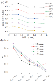
CPU的工作温度直接影响其工作效率, 因此, CPU的温度均匀性是衡量液冷板散热性能的重点之一。不同进口温度下, CPU的温度不均匀系数随流量的变化情况如图2a所示, 从图中可以看出, 温度一定时, 随着流量的增大, 温度不均匀性降低, CPU的温度均匀性更高。相比流量变化的影响, 进口温度的改变对温度不均匀性的影响更为明显, 这是由于当流量一定时, 在相同的液冷板结构下, 不同进口温度的流体流经液冷板冷却CPU后, ${{T}_{cpu, max}}-{{T}_{cpu, min}}$的值几乎不变, 而进口温度越高, ${{T}_{cpu, ave}}$越大, 从而使温度不均匀系数降低。因此, 进口温度越高, 温度不均匀性越低, CPU温度分布更加均匀, 但从图2b可以看出, 随着进口温度的升高, 温度不均匀系数的改善效果逐渐降低。
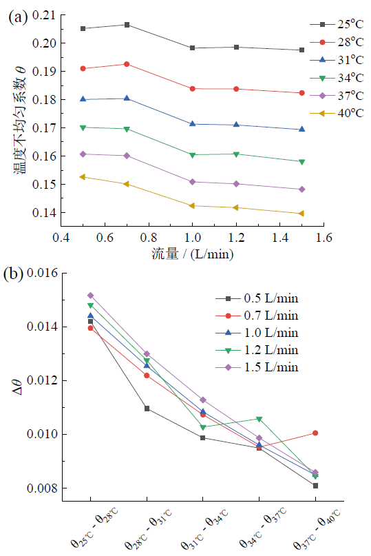 | 图2 (a)温度不均匀系数与进口流量的关系; (b)温度不均匀系数改善效果与进口温度的关系Fig. 2 (a) Relationship between temperature un-uniformity coefficient and inlet velocity; (b) relationship between temperature un-uniformity coefficient improvement and inlet temperature |
液冷板的平均热阻是目前众多学者用于评价液冷板散热性能的标准之一, 平均热阻是对流换热热阻、导热热阻以及接触热阻的总和, 本研究主要考虑液冷板自身的传热热阻, 忽略液冷板与CPU之间的接触热阻。图3为不同进口流量与温度下液冷板的平均热阻, 在不同工况下, 液冷板的平均热阻均低于0.1℃/W。当进口流量一定时, 不同的进口温度对液冷板的平均热阻几乎没有影响, 这是由于液冷板的结构不变时, ${{T}_{cpu, ave}}-{{T}_{in}}$几乎为一个定值。随着进口流量的增大, 平均热阻显著减小, 但减小的趋势逐渐变缓, 当流量达1.5 L/min, 液冷板的平均热阻小于0.04℃/W。由于加热功率为定值, 流量较小时, 进出口的温差增大, 此时液冷板集流腔底面温度较高, 热阻增大。因此, 增大流量可降低出口温度并使液冷板板底温度降低, 从而降低平均热阻。
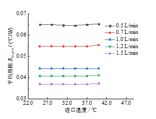 | 图 3 不同进口温度和流量下平均热阻比较Fig. 3 Comparison of average thermal resistance at different inlet temperature and flow rates |
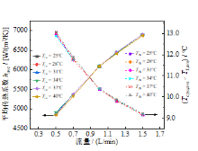
平均传热系数是评价液冷板散热性能的重要指标之一, 图4比较了不同进口流量和温度下, 液冷板的平均传热系数(实线)和传热温差(虚线)。可以观察到, 液冷板的平均传热系数随流量的增大而增大。但进口温度的变化对其影响非常小, 这是由于液冷板结构和进口流量不变时, 不同进口温度下, 换热温差${{T}_{cpu, ave}}-{{T}_{f, ave}}$基本保持不变, 根据平均传热系数的计算公式可知, 换热面积和流体的流态变化是影响液冷板换热性能的主要因素。
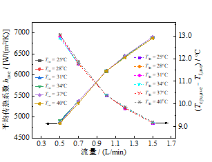 | 图 4 不同进口流量和温度下液冷板的平均传热系数和换热温差比较Fig. 4 Comparison of have and Tcpu, ave- Tf, ave of liquid cooling plate at different inlet flow rates and inlet temperature |
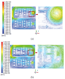
进出口方式对液冷板内流量分配特性影响很大。根据前人研究结果[20, 21], 综合考虑流动入口对流量分配均匀性的影响和安装的便捷性, 采用同侧进出口的布置方式, 流体进入液冷板时其速度方向垂直于流道的截面, 流体直接冲击分流腔底面并均匀分布到各个方向, 流体在液冷板内的流动呈现“ U” 形的流线。从模拟结果分析, 当进口流量较小时, 分流腔起到匀流的作用, 本文流量的研究范围为0.5 ~ 1.5 L/min, 为进一步探究流量对流动特性的影响, 将流量增大到1.7 L/min时, 分流腔的匀流作用不明显, 如图5所示, 冷却剂在出口侧流道回流现象剧烈, 形成了涡旋, 液冷板模拟的整体散热性能不佳, 并且使液冷板的流动阻力急剧增加。
 | 图 5 流体区域速度矢量图:(a)流量Qv = 0.5 L/min; (b)流量Qv = 1.7 L/minFig. 5 Fluid area velocity vector diagram: (a) flow rate Qv = 0.5 L/min; (b) flow rate Qv = 1.7 L/min |
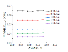
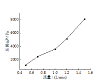
液冷板的压降Δ P与流量的关系如图6所示, 随着进口流量的增大, 沿程压降随之增大。当流量大于1.2 L/min时, 沿程压损急剧增大。由图3可知, 当流量大于1.2 L/min时, 增大流量实现强化换热的效果显著性降低, 因此, 在实际应用中, 可考虑0.7 ~ 1.2 L/min的流量范围。
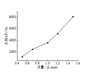 | 图6 不同进口流量下液冷板的压降比较Fig. 6 Pressure drop comparison of liquid cooling plate at different inlet flow rates |
采用数值模拟的方法对扰流空心翅片式微流道液冷板流动换热特性进行研究, 比较了不同进口温度及流量下的温度不均匀系数、液冷板的平均热阻、液冷板的平均传热系数以及流动特性, 得到的结论如下:
(1)当进口温度一定时, 流量的增大使得温度不均匀系数减小, 液冷板温度均匀性提高。
(2)当发热量一定时, 平均热阻随流量的增大而减小, 但减小趋势逐渐变缓。
(3)空心翅片结构使得液冷板内流体与固体壁面的接触面积大大增加, 从而使得液冷板的散热性能得到提高, 当进口流量大于1.2 L/min时, 可实现液冷板的平均热阻低于0.04℃/W。
(4)本文研究的液冷板结构在大进口流量的情况下易产生涡旋, 形成较大的回流区, 这将影响液冷板的流动性能, 使得液冷板的压降大幅提升。对于本文所研究的液冷板结构, 推荐流量为0.7 ~ 1.2 L/min。
| [1] |
|
| [2] |
|
| [3] |
|
| [4] |
|
| [5] |
|
| [6] |
|
| [7] |
|
| [8] |
|
| [9] |
|
| [10] |
|
| [11] |
|
| [12] |
|
| [13] |
|
| [14] |
|
| [15] |
|
| [16] |
|
| [17] |
|
| [18] |
|
| [19] |
|
| [20] |
|
| [21] |
|
| [22] |
|