

0 引言
自然界中天然气水合物储量巨大,具有能量密度高、清洁无污染等优点,被认为是一种潜在的战略性新兴能源[1,2]。目前,我国对天然气水合物的开发处于试采阶段,为实现长周期、高产气量的产业化开发,需要针对天然气水合物的成藏机理与储量评价、水合物沉积地层的地球物理学特性、水合物开采过程中储层变化规律与安全控制方案等相关问题进行深入和系统地研究。由于天然气水合物赋存环境特殊,获取含水合物沉积物实物样品的成本高、风险大,因此研究人员多在室内开展各类水合物模拟实验,如水合物成藏模式与机理实验、水合物开采实验、储层基础物性测试实验等。开展模拟实验所测量的众多参数中,含水合物沉积物的水合物饱和度是一个关键性参数。
目前实验室内测量水合物饱和度的手段主要有电阻率法[3,4]、声速法[5]、计算机断层扫描成像(computed tomography, CT)技术[6,7]、时域反射法[8](time domain reflectometry, TDR)等。电阻率法需要测量含水合物沉积物的电阻率并结合阿尔奇公式对饱和度进行计算。由于水合物生成/分解过程导致孔隙水电导率发生变化,因此沉积物的电阻率测量值会受到水合物饱和度和孔隙水电导率变化的共同影响[4]。声速法基于含水合物沉积物的声速测量值并结合经验或岩石物理模型对饱和度进行计算,如时间平均方程[9]、Lee权重方程[10]、等效介质理论[11]、改进的Biot-Gassmann公式[12]。但是含水合物沉积物的声速除了受到饱和度影响之外,还对沉积物的压实程度和水合物的微观分布模式具有敏感性。利用CT扫描技术可以得到沉积物的高分辨率图像,通过对图像进行处理能够直接得到含水合物沉积物中各相的空间分布、孔隙度、水合物饱和度等信息,但是CT技术所观测的样品尺寸较小、测试成本较高、实时性差,而且其分析结果严重依赖于图像处理方法,如在灰度图像处理时阈值的选取将直接影响饱和度的测量结果(因为水与水合物密度接近)。TDR技术通过测量电磁波在沉积物样品中的传播速度和衰减程度分别获取样品的介电常数和电导率参数,分别利用两个参数均能够建立水合物饱和度模型,并且为基于双参数联合评价水合物饱和度提供了可能。此外,在TDR测量频段(通常为10 ~ 1 500 MHz[13,14])内沉积物样品的介电常数几乎不受孔隙水离子浓度的影响[15],因此适用于水合物生成分解动态过程的测量。
TOPP等[16]利用TDR技术测量了土壤的介电常数,建立了描述表观介电常数和土壤体积含水量的经验公式。DALTON等[17]、DASBERG等[18]采用二针式TDR探头同时测量了土壤表观介电常数和电导率,证明了利用TDR技术可以同时测量土壤体积含水量和电导率。CHEN等[19,20]基于表面反射法实现了对高电导率土体介电常数的测量。将TDR技术分别应用于土体含水量与干密度的联合监测[21]、岩土变形与边坡稳定性监测[22,23]、高有机质含量填埋垃圾的含水量测量[24]、地下水污染勘察[25]等领域,取得了良好的测量效果。WRIGHT等采用TDR技术测量了沉积物的体积含水量,建立了含水量与表观介电常数的经验关系式[8]。胡高伟等[26]采用加绝缘套管的TDR探针对高盐分模拟沉积物的介电常数进行了测量,针对不同的孔隙水盐度(最高3.5%氯化钠水溶液)分别建立了介电常数与含水量之间的经验关系式。孙中明等[27]针对“四氢呋喃(tetrahydrofuran, THF)水溶液+水合物”体系建立了基于介电常数计算水合物含量的经验关系式。
针对含水合物沉积物这一复杂介质,目前的研究通过分析TDR响应仅仅获取了介电常数并建立了其与含水量/含水合物量之间的经验模型,而忽略了对电导率参数的获取与利用。因此,针对沉积物中水合物饱和度的测量问题,立足于TDR技术对介电常数和电导率双参数进行测量的优点,本文提出基于双参数的水合物饱和度评价方法,并在开展THF水合物模拟实验的基础上建立基于介电常数和电导率的饱和度计算模型,以期为提高实验室内水合物饱和度测量可靠性和准确度提供新途径。
1 实验部分
1.1 TDR双参数测量原理
$ V_{\mathrm{p}}=\frac{2 L}{\Delta t}$ (1)
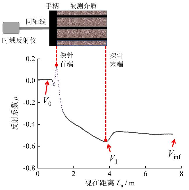
Fig. 1 Typical structure of a three-rod TDR probe and waveform diagram图1 典型三针式TDR探头结构与波形示意图 |
表观介电常数Ka与Vp的关系为:
$ \sqrt{K_{\mathrm{a}}}=\frac{c}{V_{\mathrm{p}}}$ (2)
式中:c为电磁波在真空中的传播速度。联立式(1)和式(2)可得被测介质的Ka为[30]:
$ \sqrt{K_{\mathrm{a}}}=\frac{c \Delta t}{2 L}$ (3)
将式(3)中的cΔt/2计算后以长度单位的形式在波形图上进行显示,此长度称为视在距离La,此时被测介质Ka的计算式为:
$ \sqrt{K_{\mathrm{a}}}=\frac{L_{\mathrm{a}}}{L}$ (4)
$ \sigma=\left(\frac{\varepsilon_{0} c}{L}\right)\left(\frac{Z_{\mathrm{TDR}}}{Z_{0}}\right)\left(\frac{2 V_{0}}{V_{\mathrm{inf}}}-1\right)$ (5)
式中:ε0 = 8.85 × 10⁻¹² F/m,为真空中介电常数;Z0为测试系统输出阻抗(通常为50 Ω),ZTDR是探针特征阻抗,与探针结构有关;V0是入射脉冲电压,Vinf是在多次反射停止后返回时域反射仪的电压,NOBORIO[33]认为Vinf的位置应比La长10倍。反射电压V与反射系数ρ的关系为:
$ \frac{1-\rho_{\mathrm{inf}}}{1+\rho_{\mathrm{inf}}}=\frac{2 V_{0}-V_{\mathrm{inf}}}{V_{\mathrm{inf}}}=\frac{2 V_{0}}{V_{\mathrm{inf}}}-1$ (6)
联立式(5)和式(6),则可计算得到σ[34]:
$ \sigma=\frac{K_{\mathrm{P}}}{Z_{0}} \frac{1-\rho_{\mathrm{inf}}}{1+\rho_{\mathrm{inf}}}$ (7)
式中:KP = ε0cZTDR/L为探针的几何常数,m-1;ρinf为经过多次反射后电压稳定时的反射系数。
CASTIGLIONE等[35]提出在计算电导率时应考虑电磁脉冲在线路传输过程中的损耗,使用式(8)中经校正的反射系数ρscaled替代式(7)中的ρinf,最终通过分析TDR反射波形并采用式(9)来计算被测介质的电导率σTDR。
$ \rho_{\text {scaled }}=2\left(\frac{\rho_{\text {inf }}-\rho_{\text {open }}}{\rho_{\text {open }}-\rho_{\text {short }}}\right)+1$ (8)
$ \sigma_{\mathrm{TDR}}=\frac{-K_{P}}{Z_{0}} \frac{\rho_{\text {open }}-\rho_{\text {scaled }}}{\rho_{\text {short }}-\rho_{\text {scaled }}}$ (9)
式中:ρshort和ρopen分别为探针末端短路和开路时的反射系数。
1.2 实验装置
甲烷在水中溶解度较低,获取高水合物饱和度的样品需要时间较长,并且甲烷水合物的空间分布依赖于初始状态下甲烷气和孔隙水的位置,导致样品的重复性较差,不利于研究水合物饱和度与测量信号之间的定量关系,所以诸多研究人员以THF为客体分子制备水合物来模拟甲烷水合物[4,36-41]。THF可与水互溶,水合物生成后能够在沉积物孔隙中均匀分布[42],并且THF水合物在标准大气压条件下的相平衡温度为4.4℃。通过调节THF与水的比例,可以人为控制所生成水合物的饱和度。鉴于上述优点,本文以THF水合物为研究对象开展模拟实验与测试。图2为开展THF水合物生成/分解模拟实验与TDR测试的实验装置,主要包含反应釜、恒温箱和TDR/温度参数测量单元。
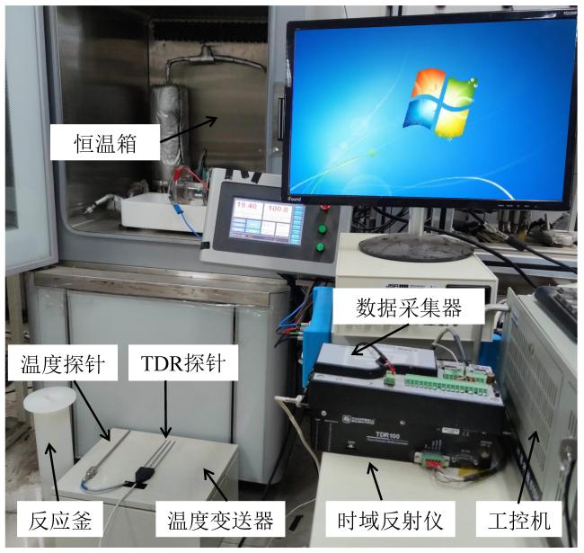
Fig. 2 Picture of experimental setup图2 实验装置照片 |
反应釜采用具有良好绝缘性与耐腐蚀性的聚丙烯材料,釜体内半径为4 cm、高32 cm、釜体厚度为3 mm。反应釜端盖中间部位开孔以便于插入TDR探针和温度传感器。温度传感器为A级Pt100热电阻(天津今明仪器有限公司),变送器为三线制温度变送器(南京卓欧自控科技有限公司),温度测量误差低于0.2℃。TDR测量系统为Campbell公司生产,主要包括稳压电源、TDR100时域反射仪、CR800 Series数据采集器、同轴传输线和TDR探头。基于系统自带软件(PC-TDR与PC200W)对TDR系统进行配置与控制,通过数据采集卡PCI-1713和自主编制的测控软件来实现温度的采集。
1.3 实验方案
采用经过筛选的天然海砂来模拟沉积物,以分析纯氯化钠和去离子水来配制孔隙水,将分析纯THF与上述孔隙水按比例混合来配制THF水溶液。
实验与测试的具体步骤如下:
(1)使用60 ~ 80目筛网对天然海砂进行筛选、冲洗和烘干,量取实验所需体积的干燥海砂待用。
(2)根据实验设定的水合物饱和度确定THF与去离子水的质量(与水合物饱和度100%、80%、60%和40%相对应的THF与去离子水物质的量比值分别为1∶17、1∶22.4、1∶31.3和1∶49.3)以及完全反应后剩余水的量。
(3)用电子天平分别称取去离子水、THF和NaCl,并依次置入烧杯中,用玻璃棒将三者搅拌混合,使THF和NaCl充分溶解于蒸馏水中,搅拌时需注意密封烧杯以防止THF的挥发。
(4)将海砂分层填入反应釜内,每填入一层海砂则注入一定量的THF盐水溶液,保证海砂孔隙持续处于水饱和状态。待反应釜装满后,将TDR探针和温度探针插入反应釜内,将反应釜静置至少24 h。
(5)将反应釜放入空气浴恒温箱,将温度设定为0℃后开启温度采集软件和TDR系统控制软件,对THF水合物生成过程中的温度和TDR波形数据进行连续采集。
(6)THF水合物完全生成后关闭恒温箱,进行THF水合物升温分解过程实验测试。将上述实验步骤重复1 ~ 2次,完成重复实验与参数测试。
2 模拟沉积物介电常数和电导率分析
2.1 水饱和模拟沉积物
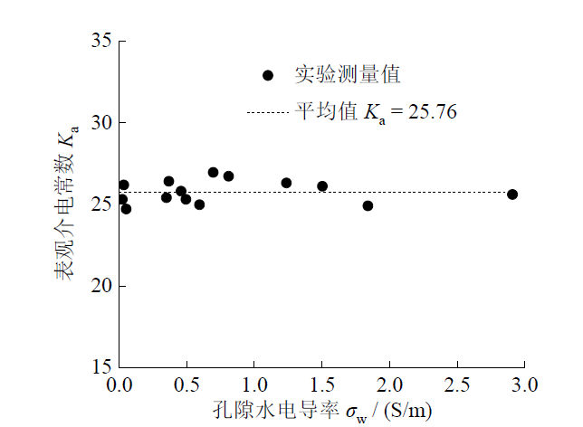
Fig. 3 Apparent dielectric constant of water-saturated sediments图3 水饱和沉积物表观介电常数 |
阿尔奇公式是电法测井技术中定量评价储层含油/水饱和度的常用模型[43],阿尔奇公式中水饱和储层电导率σ0与孔隙水电导率σw的关系式为:
$ \sigma_{0}=\frac{\sigma_{\mathrm{w}}}{F}$ (10)
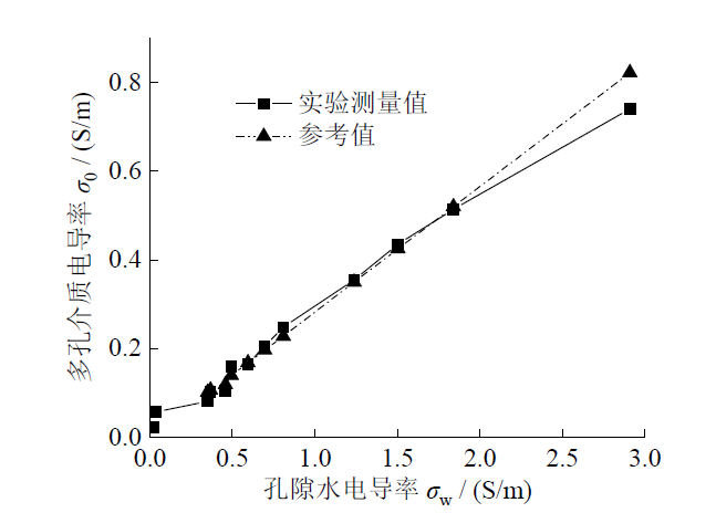
Fig. 4 Conductivity of water-saturated sediments图4 水饱和沉积物电导率 |
分析图4可知:在孔隙水电导率σ = 0.25 ~ 3 S/m时,TDR测量电导率值与参考值的平均相对偏差为1.66%;在σ = 0.023 ~ 0.25 S/m范围内,TDR测量值与孔隙水电导率呈现非线性关系,其原因在于该范围内颗粒表面电导率占比随着孔隙水电导率的降低而逐渐增大。
2.2 含水合物模拟沉积物
在孔隙水分别为去离子水和质量分数为0.5%的NaCl溶液的条件下,分别进行了水合物饱和度为0、40%、60%、80%和100%的五组THF水合物实验,分析了水合物饱和度对TDR测量的沉积物介电常数和电导率的影响。
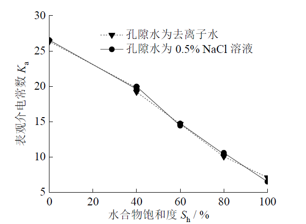
Fig. 5 Apparent dielectric constant of sediments at different hydrate saturations图5 不同水合物饱和度条件下沉积物表观介电常数 |
图6展示了两种孔隙水条件下TDR测量的沉积物电导率随水合物饱和度的变化情况。由图可知:当孔隙水为去离子水时,沉积物电导率始终稳定在约0 S/m;当孔隙水为0.5%的NaCl溶液时,沉积物电导率随水合物饱和度的增加呈现出指数函数形式降低的趋势;在100%水合物饱和度时两种情况下的沉积物电导率近似相等。
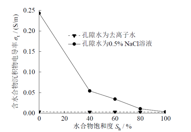
Fig. 6 Conductivity of sediments at different hydrate saturations图6 不同水合物饱和度条件下沉积物电导率 |
3 水合物饱和度计算模型
3.1 基于介电常数的模型
Topp经验公式:
$ \begin{array}{c}\theta_{\mathrm{V}}=-5.3 \times 10^{-2}+2.92 \times 10^{-2} K_{\mathrm{a}}- \\5.5 \times 10^{-4} K_{\mathrm{a}}^{2}+4.3 \times 10^{-6} K_{\mathrm{a}}^{3}\end{array}$ (11)
Wright经验公式:
$ \begin{array}{r}\theta_{\mathrm{V}}=-11.9677+4.506072566 K_{\mathrm{a}}- \\0.14615 K_{\mathrm{a}}^{2}+2.1399 \times 10^{-3} K_{\mathrm{a}}^{3}\end{array}$ (12)
Lichteneker-Rother(LR)模型:
$ \theta_{\mathrm{V}}=\frac{K_{\mathrm{a}}^{\alpha}-(1-\varphi) \varepsilon_{\mathrm{s}}^{\alpha}-\varphi \varepsilon_{\mathrm{h}}^{\alpha}}{\varepsilon_{\mathrm{w}}^{\alpha}-\varepsilon_{\mathrm{h}}^{\alpha}}$ (13)
Maxwell-DeLoor(MD)模型:
$ \theta_{\mathrm{v}}=\frac{3\left(\varepsilon_{\mathrm{s}}-K_{\mathrm{a}}\right)+2 \varphi\left(\varepsilon_{\mathrm{h}}-\varepsilon_{\mathrm{s}}\right)-K_{\mathrm{a}} \varphi\left(\frac{\varepsilon_{\mathrm{s}}}{\varepsilon_{\mathrm{h}}}-1\right)}{K_{\mathrm{a}}\left(\frac{\varepsilon_{\mathrm{s}}}{\varepsilon_{\mathrm{w}}}-\frac{\varepsilon_{\mathrm{s}}}{\varepsilon_{\mathrm{h}}}\right)+2\left(\varepsilon_{\mathrm{h}}-\varepsilon_{\mathrm{w}}\right)}$ (14)
式中:εs、εw、εh分别为海砂颗粒、水和THF水合物的相对介电常数(εs = 4.5、εw = 80、εh = 3.0)[4],$\theta_{V}$为体积含水量($ S_{\mathrm{h}}=1-\theta_{\mathrm{v}} / \varphi$)。LR模型将混合物的介电常数看作各组分介电常数的加权平均值,理论上α的取值范围为 -1 ≤ α ≤ 1。当α取值为0.5时,LR模型称作复折射系数法(complex refractive index method, CRIM)模型。
利用TDR测量实验数据对LR模型的α进行最小二乘拟合,即在其理论取值范围(-1 ≤ α ≤ 1)内寻找使得误差平方和最小的α,最终得到α = 0.7。图7将Topp经验公式、Wright经验公式、LR模型(α = 0.7)、CRIM模型、MD模型的Ka计算结果以及本文TDR实验测量结果进行了对比。LR模型(α = 0.7)和MD模型均与实验数据吻合度较高,而CRIM模型、Topp经验公式、Wright经验公式计算值显著低于实验值。针对不同的含水合物沉积物,直接采用经验公式(Topp、Wright经验公式)以及CRIM模型将会导致较大的误差。CRIM模型可看作LR模型的特例,BROVELLI等[47]指出α与阿尔奇公式中胶结指数m存在一定的联系,因此α是与多孔介质几何结构有关的参数。MD模型是基于对多孔介质结构的简化假设而推导出的理论模型,不包含拟合参数,因此其适用范围受到一定的限制。综上所述,采用LR模型(α = 0.7)作为计算水合物饱和度的最佳模型,即将α = 0.7代入式(13)得到式(15):
$S_{\mathrm{h}}=-0.1293 K_{\mathrm{a}}^{0.7}+1.334$ (15)
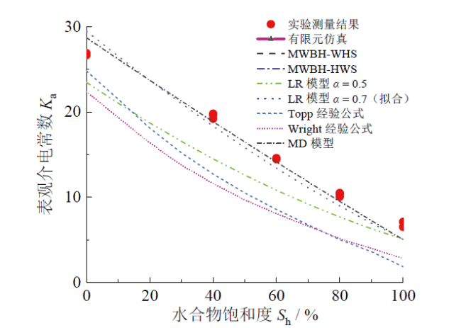
Fig. 7 Comparison of results from dielectric-constant models at different hydrate saturations图7 不同水合物饱和度条件下介电常数模型计算结果对比 |
3.2 基于电导率的模型
当模拟沉积物中含有水合物时,可将阿尔奇公式中油的参数替换为水合物的参数。
$I=\frac{\sigma_{0}}{\sigma_{\mathrm{t}}}=\frac{b}{S_{\mathrm{w}}^{n}}$ (16)
式中:I为电导率增大指数;σt为沉积物电导率;Sw为含水饱和度;b、n分别为岩性系数和饱和度指数。为了求解岩性系数b和饱和度指数n,将式(10)与式(16)联立,结合含水饱和度和水合物饱和度的关系(Sh = 1 - Sw),进而得到式(17)和式(18)。
$\frac{\sigma_{\mathrm{w}}}{\sigma_{\mathrm{t}}}=\frac{a b}{\varphi^{m} S_{\mathrm{w}}^{n}}$ (17)
$S_{\mathrm{h}}=1-\left(\frac{a b \sigma_{\mathrm{t}}}{\varphi^{m} \sigma_{\mathrm{w}}}\right)^{\frac{1}{n}}$ (18)
对式(17)两边同时取对数,并将a = 1和φ = 0.4代入。当孔隙水电导率σw = 0.797 S/m、m已知(m = 1.40)时,在双对数坐标系下,ln(σw/σt) 与ln(1/Sw) 呈现近似线性关系(如图8所示)。经线性拟合得式(20),对比式(19)和式(20)可得n = 1.85,b = 1.14。
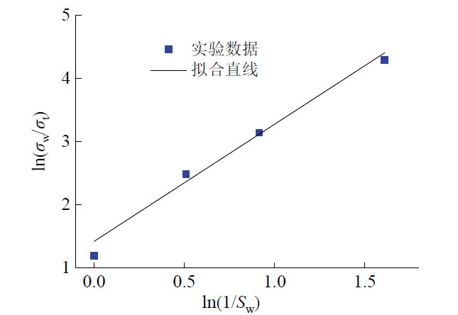
Fig. 8 Fitting for parameters of Archie’s model based on experimental data图8 基于实验数据拟合获取阿尔奇模型参数 |
$\ln \left(\frac{\sigma_{\mathrm{w}}}{\sigma_{\mathrm{t}}}\right)=n \ln \left(\frac{1}{S_{\mathrm{w}}}\right)-m \ln (0.40)+\ln (b)$ (19)
$\ln \left(\frac{\sigma_{\mathrm{w}}}{\sigma_{\mathrm{t}}}\right)=1.85 \ln \left(\frac{1}{S_{\mathrm{w}}}\right)+1.42$ (20)
将m、n和b的值代入式(18),、可得到基于电导率的水合物饱和度计算模型,即式(21):
$S_{\mathrm{h}}=1-\left(\frac{1.14 \sigma_{\mathrm{t}}}{\sigma_{\mathrm{w}} \varphi^{1.40}}\right)^{\frac{1}{1.85}}$ (21)
3.3 模型的饱和度计算结果讨论
能够同时获得含水合物沉积物的表观介电常数和电导率是TDR技术的独到优势,这为利用TDR响应分别建立基于介电常数和电导率的水合物饱和度计算模型提供了前提。利用上文所建立的两个模型分别计算沉积物中水合物饱和度,在图9中进行了比较。分析图9可知,两个饱和度计算模型的计算结果相当一致;表观介电常数模型和电导率模型计算结果的均方根误差分别为2.37%和4.71%。表观介电常数模型的性能略优于电导率模型,水合物饱和度较高时电导率模型的准确度较低。分析其原因为:水合物饱和度较高时,含水合物沉积物电导率较低且电流导通路径复杂,电导率测量值相对误差较大;水合物饱和度为100%时,理论上电导率接近0,此时的电导率测量数据无法应用于建模过程中,所以建立电导率模型时所采用的数据点相对较少,导致模型参数适应性相对较差。
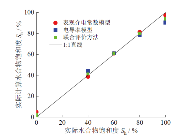
Fig. 9 Comparison of results from the dielectric-constant- based and conductivity-based hydrate-calculation models and joint assessment method图9 基于介电常数和电导率的饱和度计算模型以及联合评价方法的结果对比 |
基于TDR技术对介电常数和电导率两个参数进行测量的过程相互独立,因此本文对两个模型所得到的饱和度计算结果各赋以50%的权重,对结果进行融合处理以实现对水合物饱和度的联合评价计算(图9)。经计算,利用联合评价方法所得到的水合物饱和度均方根误差为3.06%,即处于两个模型的误差之间。
以上建立了基于TDR测量的表观介电常数和电导率的水合物饱和度计算模型,通过模型运算获得了一致性较高且误差较低(均方根误差低于5%)的饱和度计算结果,同时也展示了基于TDR双参数对水合物饱和度进行联合评价的潜力。下一步需要从以下方面继续开展研究工作:开展多饱和度条件下THF水合物实验测试,获得足够多的实验数据以提高饱和度计算模型(尤其是基于电导率的模型)的准确性;开展含黏土模拟沉积物条件下THF水合物实验测试,建立相应的基于双参数的饱和度计算模型;将基于TDR双参数的饱和度联合评价方法推广应用到含甲烷水合物沉积物。
4 结论
立足于TDR技术同时测量含水合物沉积物表观介电常数和电导率双参数的优点,提出了基于双参数的水合物饱和度评价方法,建立了基于介电常数和电导率的饱和度计算模型。得到以下结论:
(1)利用Lichteneker-Rother模型和Maxwell- DeLoor模型能够准确地描述TDR表观介电常数与水合物饱和度之间的定量关系。
(2)水合物饱和度较高时,沉积物电导率较低、TDR电导率测量值误差较大,水合物饱和度100%时的测量数据无法应用,导致阿尔奇公式中参数的适应性较差。
(3)基于TDR响应的双参数联合评价水合物饱和度的方法为提高评价结果的准确度和可靠性提供了新途径。
