

0 引言
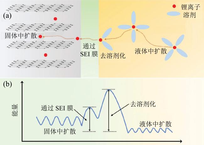
Fig. 1 (a) The charging process diagram of Li-ion battery; (b) the energy barriers diagram of Li-ion battery at different charging process (modified from reference [23])图1 (a)锂离子电池充电过程示意图;(b)充电过程不同阶段能量势垒示意图(修改自文献[23]) |
1 锂离子电池快充电解液改善途径
1.1 改善电解液扩散速度
| 溶剂种类 | 结构 | 溶剂名称 | 熔点/℃ | 沸点/℃ | 闪点/℃ | 介电常数/(F/m) |
|---|---|---|---|---|---|---|
| 碳酸脂 | 环状 | EC | 36.4 | 248.0 | 150.0 | 89.8 |
| 碳酸丙烯酯 | -48.8 | 242.0 | 135.0 | 64.9 | ||
| 碳酸丁烯酯 | -53.0 | 240.0 | 135.0 | 53.0 | ||
| VC | 22.0 | 162.0 | 73.0 | 52.0 | ||
| 链状 | DMC | 4.6 | 91.0 | 15.0 | 3.1 | |
| DEC | -74.3 | 126.0 | 33.0 | 2.8 | ||
| EMC | -53.0 | 110.0 | 23.0 | 2.9 | ||
| 羧酸酯 | 链状 | MF | -99.0 | 32.0 | -32.0 | 8.5 |
| MA | -98.0 | 57.0 | -10.0 | 6.7 | ||
| PA | -92.5 | 101.6 | 14.0 | 6.3 | ||
| EP | -73.5 | 99.1 | 12.2.0 | 5.7 | ||
| MB | -84.0 | 102.0 | 11.0 | 5.6 | ||
| EA | -84.0 | 77.0 | -4.0 | 6.4 | ||
| ML | -24.0 | 196.0 | 66.9 | 12.1 | ||
| MP | -22.0 | 135.0 | 39.0 | 36.7 |
注:碳酸乙烯酯(ethylene carbonate, EC)、碳酸亚乙烯酯(vinylene carbonate,VC)、碳酸二甲脂(dimethyl carbonate, DMC)、碳酸二乙脂(diethyl carbonate, DEC)、乙基甲基碳酸脂(ethyl methyl carbonate, EMC)、甲酸甲脂(methyl formate, MF)、乙酸甲脂(methyl acetate, MA)、乙酸丙脂(propyl acetate, PA)、丙酸乙脂(ethyl propanoate, EP)、丁酸甲脂(methyl butyrate, MB)、乙酸乙脂(ethyl acetate, EA)、乙酰丙酸甲酯(methyl levulinate, ML)、丙酮酸甲酯(methyl pyruvate, MP)。 |
| 电解液 (摩尔比为1∶1) | 浓度/ (mol/dm3) | 黏度/ (mPa∙s) | 离子导电/ (mS/cm) | 溶剂自扩散系数/ (× 10-7 cm2/s) | 锂离子自扩散系数/(× 10-7 cm2/s) | 阴离子自扩散系数/(× 10-7 cm2/s) | 玻璃化转变温度/℃ |
|---|---|---|---|---|---|---|---|
| Li[FSA]∶MP | 5.58 | 1 220 | 0.43 | 0.20 | 0.21 | 0.16 | -43.7 |
| Li[FSA]∶MA | 5.08 | 270 | 1.51 | 0.61 | 0.70 | 0.60 | -53.3 |
| Li[FSA]∶ML | 4.69 | 1 030 | 0.37 | 0.13 | 0.15 | 0.18 | -62.9 |
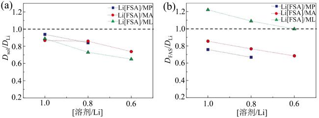
Fig. 2 Diffusivity ratios of different concentrated electrolytes at 30 °C: (a) Dsol/DLi; (b) DFSA/DLi (modified from reference [39])图2 30β℃下不同浓度电解液扩散比值:(a)Dsol/DLi; (b)DFSA/DLi(修改自文献[39]) |
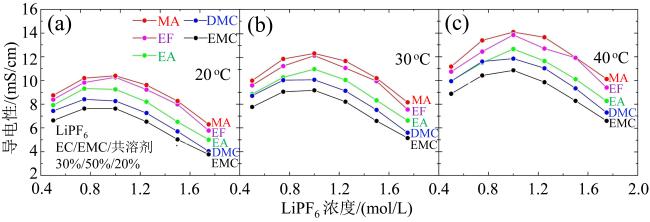
Fig. 4 The ionic conductivities of 5 electrolytes at different temperatures: (a) 20 °C; (b) 30 °C; (c) 40 °C (modified from reference [43])图4 五种电解液在不同温度下的离子导电性:(a)20β℃;(b)30β℃;(c)40β℃(修改自文献[43]) |
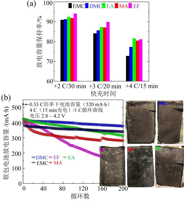
Fig. 5 (a) Discharge capacity retention diagrams of different solvents under different rates; (b) long-term cycling performance of the pouch cell under fast charging conditions with different electrolytes and Li plating diagrams of graphite electrodes (modified from reference [43])图5 (a)不同溶剂在不同充电倍率下放电容量保持率;(b)不同溶剂软包电池在快充条件下长期循环性能图及负极石墨电极析锂图(修改自文献[43]) |
1.2 降低去溶剂化势垒
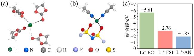
Fig. 6 (a) The typical Li+-solvation structure in the EC/DMC system; (b) the typical Li+-solvation structure in the AN-HCE and AN-DHCE systems; (c) the binding energies between Li+ and solvents in three different electrolytes (modified from reference [47])图6 (a)EC/DMC体系电解液中Li+-溶剂结构图; (b)AN/HCE和AN/DHCE体系电解液中Li+-溶剂结构图;(c)三种电解液中溶剂化Li+ 的结合能(修改自文献[47]) |
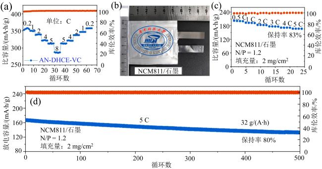
Fig. 7 (a) Rate performance for lithiation of graphite; (b) optical picture of pouch NCM811/graphite cell; (c) rate performance of pouch NCM811/graphite cell; (d) capacity retention of pouch NCM811/graphite cell at the rate of 5 C (modified from reference [47])图7 (a)锂石墨材料倍率性能;(b)NCM811/石墨软包电池照片图;(c)NCM811/石墨软包电池倍率性能; (d)NCM811/石墨软包电池5 C倍率下的容量保持率 (修改自文献[47]) |
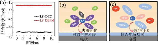
Fig. 8 (a) Binding energy of Li+ with two solvents in the electrolytes; (b) schematic diagram of the desolvation process of Li+ in the commercial electrolyte; (c) schematic diagram of the desolvation process of Li+ in the FCE electrolyte (modified from reference [48])图8 (a)两种电解液中锂离子与溶剂分子结合能图;(b)商用DEC电解液中锂离子去溶剂化示意图;(c)FEC电解液中锂离子去溶剂化示意图(修改自文献[48]) |
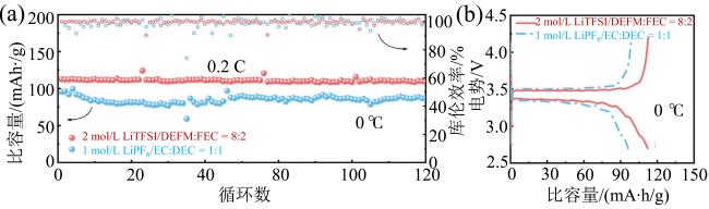
Fig. 9 (a) Cycling performances in different electrolytes at 0 °C; (b) the initial charge-discharge curves of full cells using different electrolytes at 0 °C (modified from reference [48])图9 (a)0β℃下不同电解液电池循环性能;(b)0β℃下不同电解液全电池首次充放电曲线(修改自文献[48]) |
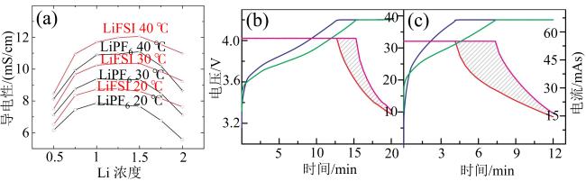
Fig. 10 (a) Conductivity of LiFSI and LiPF6 in EC:EMC as function of concentration and temperature; voltage and current versus charging time for cells charged at 3 C (b) and 5 C (c) (modified from reference [52])图10 (a)LiFSI和LiPF6电解液在EC∶DEC溶剂中的导电性随浓度和温度变化图;3 C(b)和5 C(c)下电池充电时电压、电流与充电时间关系曲线(修改自文献[52]) |
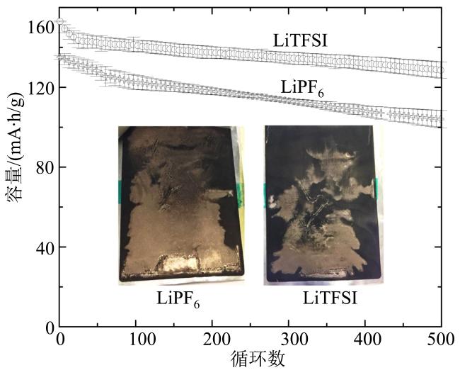
Fig. 11 Long term cycling performance of the cells with LiFSI and LiPF6 electrolytes with 12 minutes fast charging (inserted photos show the extent of Li plating on each graphite electrode) (modified from reference [52])图11 LiFSI和LiPF6电解液电池在12 min下快充长期循环图(插图为电池循环后负极析锂程度图)(修改自文献[52]) |
1.3 优化SEI膜
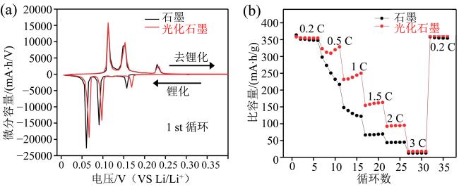
Fig. 12 (a) dQ/dV profiles of bare graphite and photo-graphite half-cells during the initial cycles at 0.1 C (35 mA/g); (b) rate capability results of bare graphite and photo-graphite half-cells (modified from reference [59])图12 (a)石墨负极和光化学石墨负极半电池在0.1 C(35 mA/g)下的dQ/dV曲线图;(b)石墨负极和光化学石墨负极半电池在同倍率下的循环结果(修改自文献[59]) |
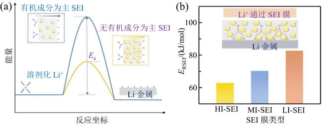
Fig. 13 (a) Ea schematic illustration of organic-rich and inorganic-rich SEI in the interfacial journey of Li+; (b) comparisons of activation energy of ion transport across different SEI (modified from reference [60])图13 (a)Li+ 通过富含有机成分和无机成分的SEI时的Ea示意图;(b)离子通过不同SEI时的活化能比较图(修改自文献[60]) |
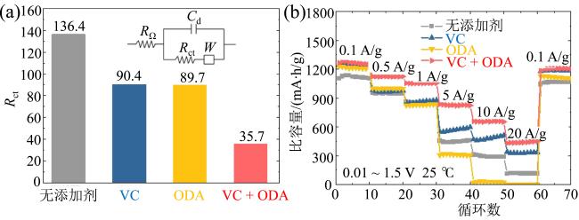
Fig. 14 (a) Rct value with different additive; (b) rate capability of the Li||Ti-SiOx@C half cells in the different electrolytes under various current densities (modified from reference [72])图14 (a)不同添加剂电解液电池拟合后Rct值; (b)注入不同添加剂电解液半电池Li||Ti-SiOx@C在不同倍率下的性能(修改自文献[72]) |
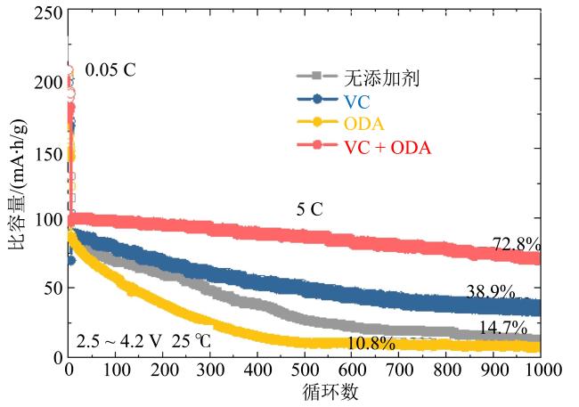
Fig. 15 Cycling performance of the NCM-811||Ti-SiOx@C full cells in the different electrolytes at 5 C (modified from reference [72])图15 在NCM-811||Ti-SiOx@C电池体系下不同电解液以5 C倍率进行长循环的曲线图(修改自文献[72]) |
