

0 引言
氢气作为一种清洁高效的能源载体,具有清洁、零碳排放、热值高、来源广泛等特点,被誉为“21世纪能源”,对缓解世界能源危机和环境污染具有积极作用[1]。氢气的制取可以由多种方式实现,如化石燃料制氢、生物质制氢、电解水制氢以及其他方式。化石燃料制氢工艺成熟,目前是氢气的主要生产方式[2],但其依赖于化石燃料且会产生温室效应。电解水制氢具有可持续和环保的优势[3],但耗电量大,成本较高。1964年FUNK等[4]提出了热化学循环水分解制氢的概念,即水和中间反应物在较低温度下发生一系列反应,中间反应物不断进行氧化-还原循环,最终只有水被消耗分解成氢气和氧气。在众多循环中,热化学碘硫循环制氢由于反应步骤简单、可与核能匹配、成本低廉、热效率较高和易于实现工业化大规模生产等优点,被视为最具发展前景的制氢技术之一[5]。碘硫循环过程由Bunsen反应、HI分解反应和H2SO4分解反应组成,其中H2SO4分解反应分为硫酸初步分解和SO3催化分解两步。相关反应方程式如式(1)~ 式(4)所示:
$ 2 \mathrm{H}_{2} \mathrm{O}+\mathrm{I}_{2}+\mathrm{SO}_{2} \xrightarrow{80 \sim 120^{\circ} \mathrm{C}} \mathrm{H}_{2} \mathrm{SO}_{4}+2 \mathrm{HI}$ (1)
$ 2 \mathrm{HI} \xrightarrow{300 \sim 500^{\circ} \mathrm{C}} \mathrm{H}_{2}+\mathrm{I}_{2}$ (2)
$ \mathrm{H}_{2} \mathrm{SO}_{4} \xrightarrow{350 \sim 500^{\circ} \mathrm{C}} \mathrm{H}_{2} \mathrm{O}+\mathrm{SO}_{3}$ (3)
$ \mathrm{SO}_{3} \xrightarrow{800 \sim 900^{\circ} \mathrm{C}} \mathrm{SO}_{2}+\frac{1}{2} \mathrm{O}_{2}$ (4)
在上述反应中,硫酸的两步分解过程由于反应温度要求苛刻,涉及复杂的物理化学过程,是影响整个系统制氢效率的重要部分。因此,对硫酸分解过程进行研究具有重要意义。
硫酸分解器的结构设计对硫酸的分解率具有重要影响,而数值模拟则是探究分解器内硫酸分解过程中难以直接测量的热质传递细节的重要方法。国内外学者通过数值模拟方法对硫酸分解器进行了大量研究。NAGARAJAN等[6]首次提出了一种刺刀式SiC换热器作为硫酸分解器,使用质量分数为1%的Pt/TiO2催化剂,通过Fluent多孔介质模型和组分输运模型对催化分解段进行数值模拟,研究了不同操作压力、硫酸入口流量和催化剂表面积与催化分解段体积之比对SO3分解率的影响。CHOI等[7]对其建设的单管制氢50 L/h的刺刀式硫酸分解器展开数值模拟研究,入口为纯硫酸或质量浓度为95%的硫酸溶液,使用Fluent多相流混合物模型单独研究了分解器内硫酸相变过程。模拟结果表明硫酸相变区长度约280 mm。CORGNALE等[8]通过STARCCM + 求解自定义的组分输运等方程,对使用Pt基催化剂的刺刀式硫酸分解器的催化分解段进行了数值模拟。结果表明,该反应器具有高效的分解性能,能够实现52.17%的SO3分解率。GAO等[9]通过Fluent多孔介质模型和组分输运模型研究了刺刀式硫酸分解器使用双内管结构时对SO3分解效果的优化。结果表明,相对于单内管,双内管结构分解效果有所提升,且在同等换热面积下提升效果更佳。
催化剂对硫酸分解也具有重要影响,因此研究SO3在不同催化剂下的反应动力学是准确模拟硫酸分解器内催化分解过程的必要条件。BRECHER等[10]研究了SO3在塞流式反应器中的分解过程。结果表明,硫酸分解为SO3是瞬间发生的,且在蒸发器内的非催化条件下能够实现100%的转化。而SO3分解为SO2和O2是一个动力学控制的一阶可逆反应,并且该体系远离平衡。NAGARAJAN等[6]根据GINOSAR等[11]的实验数据计算了质量分数为1%的Pt/TiO2催化剂的反应动力学参数,其中指前因子A为0.16 s-1,活化能Ea为32.67 kJ/mol。VAN DER MERWE[12]研究了极细的纯Fe2O3粉作为SO3分解催化剂的性能。通过假定反应器内的塞流条件和一级动力学,得到了反应的动力学参数,其中A为 (3±0.5) × 108 h-1,Ea为(118±23) kJ/mol。PATHAK等[13]研究了催化剂组成、尺寸和温度等对催化分解SO3效率的影响,并通过实验确定了CuFe2O4/β-SiC催化SO3分解的动力学参数,其中A为2.35 × 107 s-1,Ea为60.1 kJ/mol。
综上所述,以往硫酸分解器的数值模拟通常采用昂贵的 Pt 基催化剂,而对 SO3 催化分解反应动力学的单独研究大多停留在粉末状催化剂或商用成型的 Pt 基催化剂上。因此,为了优化设计中试乃至未来工业化规模的碘硫循环制氢系统,亟需研究成型、低成本的 SO3 催化剂的反应动力学。此外,在对硫酸分解器进行模拟时,现有文献通常假定入口为纯硫酸或质量浓度在 85%以上的浓硫酸。然而,本课题组前期在对碘硫循环制氢中试系统连续运行调试时发现硫酸闪蒸部分难以得到较高浓度的硫酸溶液[14]。因此,研究低浓度硫酸在分解器中的分解过程也具有重要的现实意义。本研究将通过实验测量成型催化剂的反应动力学参数,并通过数值模拟优化硫酸分解器的结构形式和尺寸,以增强传热效果并获得更好的经济性能。
1 催化分解反应动力学实验
1.1 实验系统
测定SO3催化分解反应动力学参数的实验系统示意图如图1所示。该实验系统主要由蠕动泵、质量流量计、电加热高温管式炉、石英反应管、冷凝器、后处理装置以及氧气分析仪组成。石英反应管外径30 mm,壁厚2 mm。电加热高温管式炉的温度控制探头保持在催化剂床层附近,以控制催化核心区的温度。
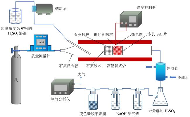
Fig. 1 Experimental system of SO3 catalytic decomposition reaction kinetics research图1 SO3催化分解反应动力学研究实验系统 |
在该实验系统中,质量浓度为97%的H2SO4溶液经由蠕动泵通入石英反应管内,在高温作用下迅速蒸发为硫酸蒸气和水蒸气。电加热高温管式炉的温度范围为750 ~ 850 ℃。N2作为载气以一定的流量通入石英反应管内,与蒸发后的硫酸蒸气和水蒸气混合。混合气体继续吸热升温,其中硫酸蒸气发生初步分解,生成SO3和水蒸气,并在进入石英填充床之前完全分解。之后,SO3、水蒸气和N2混合气体在石英填充床中充分混合均匀,并升温至外部管式炉设定的加热温度。随后,混合气体进入催化剂填充床,其中SO3在催化剂作用下发生分解反应生成SO2和O2。反应后的混合气体随后进入冷凝管中,未分解的SO3和水蒸气降温并再次结合生成硫酸蒸气,接着冷凝成液态硫酸被收集在锥形瓶中。离开锥形瓶的混合气体中仅剩N2、SO2、水蒸气和O2。SO2和水蒸气分别在NaOH洗气瓶和变色硅胶干燥瓶里被吸收,最终只有N2和O2的混合气进入氧气分析仪中。
根据氧气分析仪中测定出的O2体积分数,结合质量流量计设定的N2流量,可得到SO3催化分解后生成的O2摩尔流量$ n_{\mathrm{O}_{2}}$。根据蠕动泵通入的硫酸溶液的质量流量和浓度,可得到进入催化剂填充床前的SO3摩尔流量$ n_{\mathrm{SO}_{3}}$。然后根据式(5)计算出SO3在设定温度和给定催化剂条件下的催化分解率$ X_{\mathrm{SO}_{3}}$:
$ X_{\mathrm{SO}_{3}}=\frac{2 n_{\mathrm{O}_{2}}}{n_{\mathrm{SO}_{3}}} \times 100 \%$ (5)
1.2 实验原理
根据塞流式反应器(plug flow reactor, PFR)原理对SO3催化分解反应动力学参数进行测定。假设反应物浓度仅沿流动的轴向呈梯度变化,而在径向上浓度始终保持一致,简化后的分析模型如图2所示。在该模型中,假定在t = 0时刻,混合气体进入催化剂床层(床层长度为L),此时SO3的摩尔浓度为$ C_{\mathrm{SO}_{3}, 0}$。任意时刻t = tx 时,混合气体流动到距离入口长度为x的位置处,此时SO3的摩尔浓度为$ C_{\mathrm{SO}_{3}, x}$,反应速率为$ r_{\mathrm{SO}_{3}, x}$。在一段微元时间dt内,SO3的摩尔浓度变化量为$ \mathrm{d} C_{\mathrm{SO}_{3}}$。最终在t = tL时刻,混合气体离开催化剂床层,此时SO3的摩尔浓度为$ C_{\mathrm{SO}_{3}, L}$。
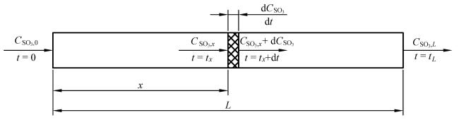
Fig. 2 Analytical model of SO3 catalytic decomposition reaction kinetics图2 SO3催化分解反应动力学分析模型 |
根据图2和微元质量守恒可以得到式(6):
$ \mathrm{d} C_{\mathrm{SO}_{3}}=r_{\mathrm{SO}_{3}, x} \mathrm{~d} t$ (6)
SO3反应速率$ r_{\mathrm{SO}_{3}, x}$与SO3的摩尔浓度$ C_{\mathrm{SO}_{3}, x}$的关系如式(7)所示。
$ r_{\mathrm{SO}_{3}, x}=-k C_{\mathrm{SO}_{3}, x}^{m}$ (7)
式中:k为SO3的反应速率常数,m为反应级数。
TAGAWA等[15]已证明SO3的催化分解反应是一级反应,因此m为1。将式(7)代入式(6)之中,并对两边同时进行积分,可以得到式(8):
$ \ln \frac{C_{\mathrm{SO}_{3}, L}}{C_{\mathrm{SO}_{3}, 0}}=-k t_{L}$ (8)
SO3的分解率$ X_{\mathrm{SO}_{3}}=\left(C_{\mathrm{SO}_{3}, 0}-C_{\mathrm{SO}_{3}, L}\right) / C_{\mathrm{SO}_{3}, 0}$,因此式(8)可进一步化简为式(9):
$ \ln \left(1-X_{\mathrm{SO}_{3}}\right)=-k t_{L}$ (9)
根据阿伦尼乌斯公式可得$ k=A \mathrm{e}^{-\frac{E_{\mathrm{s}}}{R T}}$,其中R为通用气体常数,而A和Ea即为本文所需测定的反应动力学参数。将其代入式(9),并对两边再同时取对数并进一步化简,可以得到式(10):
$ \ln \left[-\ln \left(1-X_{\mathrm{SO}_{3}}\right)\right]=\ln \left(A t_{L}\right)-\frac{E_{\mathrm{a}}}{R} \cdot \frac{1}{T}$ (10)
根据式(10),通过实验测定SO3在不同温度下的分解率,然后对$ \ln \left[-\ln \left(1-X_{\mathrm{SO}_{3}}\right)\right]$随1/T变化的散点图进行线性拟合,得到拟合线的斜率和截距,即可计算出SO3在给定催化剂下的反应动力学参数。
本次SO3催化分解反应动力学实验所使用的催化剂是成型的块状Fe2O3催化剂,其等效直径为4.5 ~ 5 mm。Fe2O3催化剂具有较好的催化活性和稳定性[16],同时成本远低于Pt基催化剂,获取来源广泛,因此是比较适合碘硫循环制氢的催化剂之一。
2 数值仿真模型
2.1 几何模型
刺刀式是最常见的硫酸分解器形式,其由内外两个同心圆管组成,外管一端呈半球形封闭,如图3所示。根据硫酸分解的全过程,刺刀式硫酸分解器两管之间的环空区域分为升温相变段、预热段和催化分解段三个部分。硫酸溶液从底部两管之间的环空区域流入,从外管加热壁和内管回流的高温气体处吸收热量,温度升高并在达到沸点后逐渐发生相变,在进入预热段之前完全蒸发成为硫酸蒸气和水蒸气的混合气体。随后气体混合物在预热段继续吸热升温,其中硫酸蒸气也开始初步分解。当离开预热段时,气体混合物温度升至750 ~ 850 ℃,硫酸蒸气也已完全分解。此后混合气体进入催化分解段,在高温和催化剂的作用下SO3发生催化分解反应,反应后的高温气体混合物从内管回流并最终离开硫酸分解器。这种刺刀式硫酸分解器全部由SiC制成,既能耐高温硫酸腐蚀,安全性较高,又能回收反应后气体的高温余热,降低硫酸分解部分的能耗。
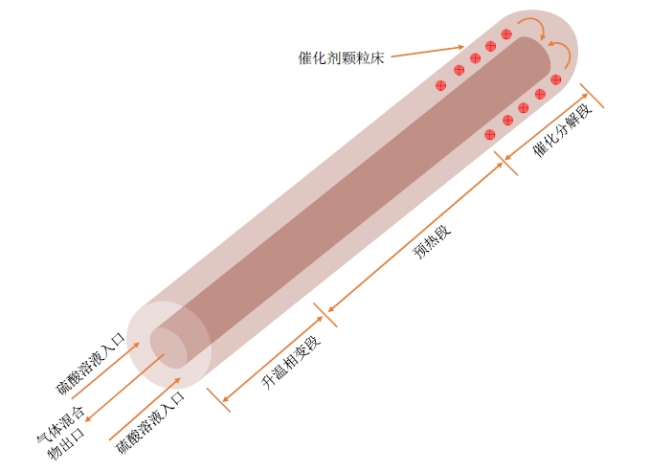
Fig. 3 Schematic diagram of bayonet sulfuric acid decomposer图3 刺刀式硫酸分解器示意图 |
由于硫酸的两步分解反应以及分解器主要的能耗都集中在预热段和催化分解段,因此仅对刺刀式硫酸分解器的预热段和催化分解段中发生的流动和传热过程进行模拟研究。以1 m3/h制氢量为目标,设计了三种结构形式的刺刀式硫酸分解器,相关尺寸和结构差异列于表1,其中结构一的内管直径是外管内径的一半,而结构二和结构三的内管截面积是外管内截面积的一半。
Table 1 Dimensions of the sulfuric acid decomposers表1 硫酸分解器的尺寸 |
| 结构形式 | 外管外径(壁厚)/mm | 内管外径(壁厚)/mm | 预热段是否填充SiC球 |
|---|---|---|---|
| 结构一 | 106(3) | 50(2) | 否 |
| 结构二 | 106(3) | 72(2) | 否 |
| 结构三 | 106(3) | 72(2) | 是 |
三种结构形式的预热段和催化分解段长度需要通过仿真研究来确定:(1)硫酸分解器设计工况为外管恒温900 ℃电加热,因此为了保证催化分解段能在800 ~ 900 ℃温度区间高效工作,需要合理设计预热段长度,使得气体混合物在离开预热段时平均温度达到850 ℃;(2)催化分解段的长度根据硫酸分解器至少达到60%催化分解率的要求来设计。
2.2 数学模型和网格划分
利用Ansys Fluent软件对2.1节建立的三种结构形式的硫酸分解器进行数值模拟,采用Fluent二维轴对称稳态模型进行相关计算。为简化计算,三种结构中的催化分解段以及结构三中填充了SiC球的预热段均被视为多孔介质。由于三种结构中流体域的最大雷诺数均在2 000以下,因此流体的流动状态均为层流。相关控制方程包括连续性方程、动量方程、能量方程和组分输运方程。
多孔介质区黏性阻力系数1/α和惯性阻力系数C2可根据Ergun公式求取:
$ 1 / \alpha=1 /\left[\left(D_{\mathrm{p}}^{2} / 150\right) \cdot\left(\varepsilon^{3} /(1-\varepsilon)^{2}\right)\right]$ (11)
$ C_{2}=\left(3.5 / D_{\mathrm{p}}\right) \cdot\left[(1-\varepsilon) / \varepsilon^{3}\right]$ (12)
式中:Dp为颗粒直径;ε为颗粒床孔隙率。本次仿真Fe2O3催化剂直径取5 mm,孔隙率为0.5;而SiC小球取直径4.5 mm,孔隙率为0.5。
非多孔介质区域以及催化分解段的多孔介质区域能量方程如式(13)所示:
$ \nabla \cdot\left(\rho c_{p} \boldsymbol{U} T\right)=\nabla \cdot\left(\lambda_{\mathrm{eff}} \nabla T\right)$ (13)
式中:ρ为流体密度;cp为流体比热容;U为流体速度;T为流体温度;λeff在非多孔介质区域为流体导热系数λf,在催化分解段为流体与多孔固体的体积平均导热系数,即$ \lambda_{\text {eff }}=\varepsilon \lambda_{\mathrm{f}}+(1-\varepsilon) \lambda_{\mathrm{s}}$。
由于SiC小球的导热系数与硫酸分解器内的气体混合物的导热系数相差极大(量级差距达到103),若继续使用多孔介质热平衡模型会带来较大误差。因此对结构三预热段部分的多孔介质区域采用非热平衡模型,能量方程如式(14)和式(15)所示:
$ \left(\rho c_{p}\right)_{\mathrm{f}} \boldsymbol{U} \cdot \nabla T_{\mathrm{f}}=\nabla \cdot\left(\varepsilon \lambda_{\mathrm{f}} \nabla T_{\mathrm{f}}\right)+h_{\mathrm{ff}} a_{\mathrm{sf}}\left(T_{\mathrm{s}}-T_{\mathrm{f}}\right)$ (14)
$ 0=\nabla \cdot\left[(1-\varepsilon) \lambda_{\mathrm{s}} \nabla T_{\mathrm{s}}\right]+h_{\mathrm{sf}} a_{\mathrm{sf}}\left(T_{\mathrm{f}}-T_{\mathrm{s}}\right)$ (15)
式中:αsf为流体与多孔固体对流换热比表面积;hsf为流体与多孔固体的对流换热系数。本文中的流体为气体混合物,故对流换热系数hsf根据WHITAKER[17]提出的实验关联式(16)来确定:
$ h_{\mathrm{sf}}=\left(0.5 R e_{\mathrm{p}}^{0.5}+0.2 R e_{\mathrm{p}}^{2 / 3}\right) P r^{1 / 3} \lambda_{\mathrm{f}} / D_{\mathrm{p}}$ (16)
式中:Rep为流体的颗粒雷诺数;Pr为流体的普朗特数。
描述硫酸两步分解反应的组分输运方程如式(17)所示,其中Ri,r为反应r中任一组分i的摩尔反应速率,可根据式(18)算出:
$ \nabla \cdot\left(\rho \boldsymbol{U} Y_{i}\right)=\nabla \cdot\left(\rho D_{\mathrm{m}, i} \nabla Y_{i}\right)+M_{\mathrm{w}, i} \sum_{r=1}^{N_{\mathrm{R}}} R_{i, r}$ (17)
$ R_{i, r}=k_{r} \prod_{j=1}^{N}\left[C_{j, r}\right]$ (18)
式中:Yi表示流体中任一组分i的质量分数;Dm,i表示组分i向流体中其他组分的质量扩散系数;Mw,i为组分i的摩尔质量;NR为总反应数;N为反应r中反应物组分的数量;Cj,r为反应r中组分j的摩尔浓度;kr为反应r的反应速率常数,通过将反应动力学参数带入阿伦尼乌斯公式中计算得出。
硫酸初步分解反应不需要催化剂,因此该步反应的动力学参数是唯一的,参考GAO等[18]的研究结果,取A和Ea分别为1.44 × 10⁷ s-1和92.13 kJ/mol。而SO3催化分解的反应动力学参数则如1.2节中所述,从实验中获取。
硫酸分解器模型的网格划分在ICEM-CFD软件中进行,采用结构化网格和非结构化网格相结合的方式,如图4所示。其中半圆形区域采用非结构化网格,其余区域均采用结构化网格,并对内外管壁附近的边界层进行了加密,保证仿真结果更加准确。
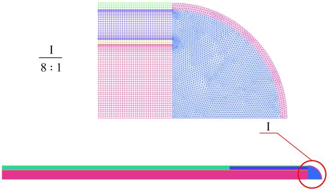
Fig. 4 Schematic diagram of the grid图4 网格示意图 |
2.3 物性参数和边界条件
硫酸分解器内的工质是硫酸蒸气、SO3、SO2、O2和水蒸气的气体混合物,由于其在分解器内的流速和压力变化较小,因此使用不可压缩理想气体模型来计算气体混合物的密度,而气体混合物的比热容、导热系数和动力黏度则由各组分对应的物性参数进行质量加权平均来求取。气体混合物内各组分的物性参数来自Fluent自带的材料库。SiC和Fe2O3固体的相关物性参数以及数值模拟的边界条件则如表2所示,其中入口气体混合物的流量根据质量浓度为60%的硫酸溶液在60%催化分解率时满足整个制氢系统1 m3/h理论制氢量的设计要求来确定。H2理论产率$ Y_{\mathrm{H}_{2}}$可由式(19)计算:
$ Y_{\mathrm{H}_{2}}=\frac{Q_{\mathrm{H}_{2} \mathrm{SO}_{4}, \mathrm{aq}} \cdot w}{M_{\mathrm{H}_{2} \mathrm{SO}_{4}}} \cdot X_{\mathrm{SO}_{3}} \cdot 22.4$ (19)
式中:$ Q_{\mathrm{H}_{2} \mathrm{SO}_{4}, \mathrm{aq}}$、w分别为硫酸溶液的质量流量和质量浓度;$ M_{\mathrm{H}_{2} \mathrm{SO}_{4}}$为H2SO4的摩尔质量;22.4 L/mol为标况下气体摩尔体积。
Table 2 Computational conditions表2 计算条件 |
| 参数 | 取值 |
|---|---|
| SiC导热系数/(W∙m-1∙K-1) | 46 |
| Fe2O3导热系数/(W∙m-1∙K-1) | 4 |
| 入口气体混合物流量/(kg∙h-1) | 12.152 8 |
| 入口气体混合物温度/K | 623.15 |
| 入口硫酸蒸气质量分数 | 0.6 |
| 入口水蒸气质量分数 | 0.4 |
| 外壁面加热温度/K | 1 173.15 |
| 压力/MPa | 0.1 |
3 结果和讨论
3.1 催化分解反应动力学参数分析
在SO3催化分解反应动力学参数测定实验中,N2流量设定为1 043 mL/min,Fe2O3催化剂填充质量为18 g左右。硫酸溶液泵入流量和反应温度条件如表3所示,包括了3种重时空速比GWHSV和5种反应温度(每个温度间隔25 K),共计15种反应条件的排列组合。
Table 3 Kinetic experimental conditions of SO3 decomposition reaction catalyzed by Fe2O3表3 Fe2O3催化SO3分解反应动力学实验条件 |
| 序号 | 泵转速/ (r/min) | 硫酸流量/ (g/min) | GWHSV/h-1 | 反应温度/K |
|---|---|---|---|---|
| 1 | 1.0 | 4.862 30 | 16.125 | 1 023 ~ 1 123 |
| 2 | 0.8 | 3.889 84 | 13.002 | 1 023 ~ 1 123 |
| 3 | 0.7 | 3.403 61 | 11.301 | 1 023 ~ 1 123 |
注:GWHSV为重时空速比,表示硫酸溶液的质量流量与催化剂的质量之比。 |
图5展示了不同GWHSV下ln[-ln(1-X)]随1/T变化的散点图和相应的拟合线。从图中可以观察到实验结果的线性拟合度较高,进一步验证了SO3催化分解反应为一级反应。
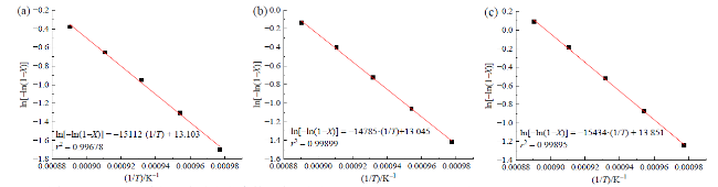
Fig. 5 Determination of kinetic parameters of SO3 decomposition reaction at different GWHSV: (a) GWHSV = 16.125 h-1; (b) GWHSV = 13.002 h-1; (c) GWHSV = 11.301 h-1图5 不同GWHSV下SO3分解反应动力学参数测定:(a)GWHSV = 16.125 h-1;(b)GWHSV = 13.002 h-1;(c)GWHSV = 11.301 h-1 |
Table 4 Kinetic parameters of SO3 decomposition reaction catalyzed by Fe2O3表4 Fe2O3催化SO3分解反应动力学参数 |
| 序号 | GWHSV/h-1 | A/s-1 | Ea/(kJ/mol) |
|---|---|---|---|
| 1 | 16.125 | 1.238 × 10⁷ | 125.64 |
| 2 | 13.002 | 1.007 × 10⁷ | 122.92 |
| 3 | 11.301 | 2.073 × 10⁷ | 128.32 |
| 平均值 | — | 1.439 × 10⁷ | 125.63 |
3.2 三种结构形式的对比分析
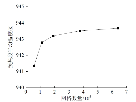
Fig. 6 Verification of the grid independence图6 网格无关性验证 |
Table 5 Length dimensions of the sulfuric acid decomposers表5 硫酸分解器的长度尺寸 |
| 结构形式 | 预热段长度/mm | 催化分解段长度/mm |
|---|---|---|
| 结构一 | 5 200 | 250 |
| 结构二 | 2 950 | 300 |
| 结构三 | 870 | 300 |
图7展示了三种结构的硫酸分解器内预热段各位置处流体的平均温度变化。图中可见,结构二的预热段中流体的温升速率显著大于结构一,而结构三又远大于结构二。结构一中,流体从入口350 ℃升温到850 ℃所需的预热段长度为5 200 mm,而结构二仅需2 950 mm,相比结构一缩短了43.27%。由此可见,在刺刀式硫酸分解器中,内管采用“半截面积”形式比“半直径”形式具有更好的传热效果。这是由于结构二相对于结构一,一方面增大了预热段中流体的流动速度,从而增大了外加热壁面向内部流体的对流换热系数;另一方面减小了预热段的径向传热间距,这两方面均有利于提高流体的温升速率。虽然结构二内管中流体回流速度相对于结构一降低,导致内管内反应后的高温流体向外侧预热段流体传热效果减弱,不利于预热段流体温升速率的提高,但是综合考虑前述两方面的改善,最终结构二的传热效果仍优于结构一。因此,采用“半截面积”形式的内管可以明显缩短整个刺刀式硫酸分解器的长度,这既有利于降低分解器的制造成本和难度,又能够降低分解器安装时的空间要求。
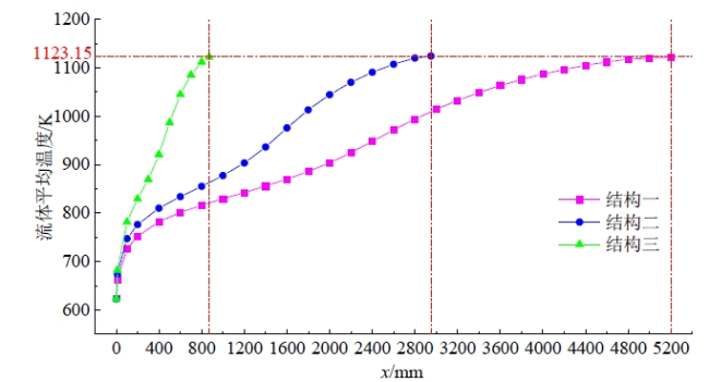
Fig. 7 Average fluid temperature change at each position of the preheating section图7 预热段各位置处的流体平均温度变化 |
虽然结构二已将预热段长度缩短至2 950 mm,但该长度仍然过长,超出了目前SiC管制造工艺的加工难度。结构三通过向预热段内填充导热系数较高的SiC小球形成球床,这一设计不仅能增大外加热壁面向内部流体的传热速率,还能在流动过程中形成涡流并相互扰动,进一步增强了流体之间的传热效果。在两种增强效果下可以极大提高预热段中流体的升温速率,并使流体温度分布更加均匀。因此在图7中,结构三所需的预热段长度从结构二的2 950 mm进一步缩短至870 mm,相比结构二缩短了70.51%,相比结构一更是缩短了83.27%。
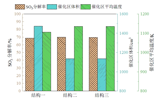
Fig. 8 SO3 catalytic decomposition rate, average fluid temperature in the catalytic section and volume of the catalytic section图8 SO3催化分解率、催化区流体平均温度和催化区体积 |
图9对比了三种结构的硫酸分解器内总的热消耗量和压降情况。可以看出,结构一至结构三所需的热功率逐渐增大,这主要是由于结构一至结构三的硫酸分解器总长度显著缩短,导致内管中反应后的高温流体的热量回收不足。尽管如此,三种结构的热流量差距并不明显,结构二相对于结构一仅增加了6%,结构三相对于结构二增加了9.5%。在硫酸分解器的总压降方面,由于结构二相对于结构一增大了环空区域流体的流速,因此结构二压降有所上升。而结构三中的预热段填充了SiC球床,导致压降相对于结构一和二有显著增加。尽管如此,结构三中的总压降也仅为5 801.2 Pa,相对于101 kPa的大气压而言,入口压力仅增大5.7%,整个硫酸分解器内部压力变化较小,仍可视为常压状态。
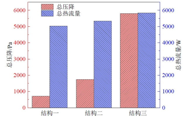
Fig. 9 Total heat flux and pressure drop in the decomposer图9 分解器内的总热流量和总压降 |
综上,为实现整个碘硫循环制氢系统1 m3/h制氢量的要求,采用结构三形式的硫酸分解器具有最佳的传热效果。相对于CORGNALE等[8]采用的结构一形式的硫酸分解器,结构三能够显著缩短分解器的总长度,并降低催化剂的用量。尽管结构三的形式会带来一定的能耗牺牲和压降增加,但其负面影响相对较小,远不及分解器尺寸缩短和催化剂用量减少所带来的益处。
3.3 不同催化区长度的影响
3.2节结果表明结构三表现出最佳的性能,因此后续仅对结构三进行研究。为了分析催化区长度对硫酸分解效率的影响,图10(a、b)展示了预热段长度保持在870 mm不变,而催化区长度在200 ~ 500 mm之间变化时,SO3催化分解率X和催化剂用量(本节用催化区体积V代替)的变化情况。为了评估在该分解器中综合考虑SO3催化分解率和催化剂用量的最佳催化区长度,采用功效系数法以解决多目标优化问题。该方法将多个指标量化到同一个程度,并得到相应的功效系数,然后将各指标的功效系数加权构造总功效系数,从而寻求最优解。c1和c2分别定义为SO3催化分解率和催化区体积的功效系数,其取值范围为0 ~ 1。如图10(c、d)所示,c1越接近1,表明SO3催化分解率越高;而c2越接近1,则表明催化区体积越小。总功效系数c定义为c = (c1c2)0.5,从图10(e)中可见,在催化区长度为333 mm时,总功效系数达到最大,此时分解器表现出最佳的经济性能。
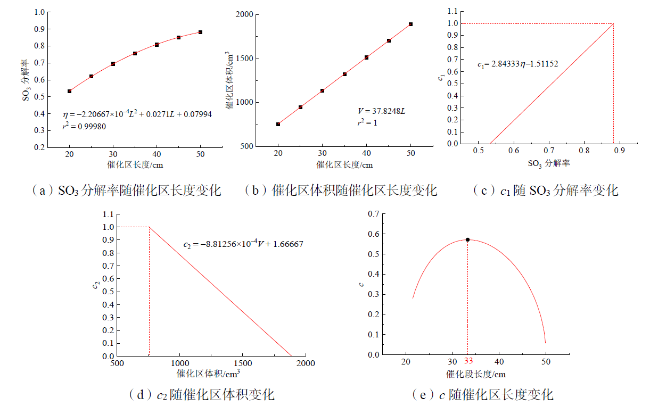
Fig. 10 Analysis of optimal catalytic length图10 最佳催化区长度分析 |
3.4 不同外壁面温度的影响
以最优尺寸下的结构三形式的硫酸分解器(预热段为870 mm,催化分解段为333 mm)为研究对象,分析外壁面温度变化对分解器运行效果的影响。图11展示了外壁面加热温度在825 ~ 900 ℃之间变化时,SO3催化分解率和对应的碘硫循环制氢系统的理论H2产率的变化情况。图中可见,随着外壁面加热温度的降低,SO3催化分解率和对应的H2理论产率也随之降低,这是由于催化区平均温度降低导致催化剂活性下降所致。在外壁面温度为900 ℃时,SO3分解率和对应的H2理论产率分别为73.73%和1.228 8 m3/h。而当加热温度降低到860 ℃时,SO3的催化分解率约为60%,此时对应的H2理论产率为1 m3/h。因此,结构三形式的硫酸分解器在外壁面温度为860 ℃及以上时均能够满足整个碘硫循环制氢系统1 m3/h的制氢量需求。
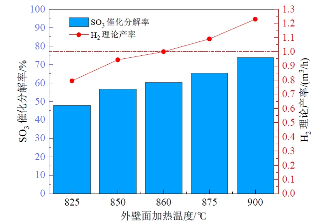
Fig. 11 Effect of outer wall temperature on SO3 catalytic decomposition rate and theoretical H2 yield图11 外壁面温度对SO3催化分解率和理论H2产率的影响 |
4 总结
设计了一款能够实现较高单管制氢量的刺刀式硫酸分解器,采用适用于碘硫循环制氢中试平台的低成本成型Fe2O3催化剂,并能在入口硫酸质量浓度为60%的条件下满足整个制氢系统1 m3/h的制氢量要求。通过数值模拟方法对硫酸分解器的结构形式和尺寸进行了优化设计,以实现更强的传热效果和更好的经济性能。主要结论如下:
(1)采用成型的低成本块状Fe2O3作为催化剂,通过实验测量和阿伦尼乌斯公式变换处理,获得了SO3催化分解反应的动力学参数,其中指前因子A为1.439 × 10⁷ s-1,活化能Ea为125.63 kJ/mol。
(2)设计的结构二传热效果优于结构一,能将预热段长度缩短43.27%,在达到相同催化分解率时所需催化剂用量减少23%。归因于结构二环空区域中流体流速更高,对流传热更强,同时降低了径向传热间距。结构三相比结构二进一步优化了预热段传热效果,预热段长度缩短70.51%,原因为SiC球床增强了流体扰动和高温壁面向预热段中流体的传热速率,带来的压降和能耗的牺牲影响较低。
(3)结构三的预热段长度设计为870 mm,催化分解段长度为333 mm时具有最佳的经济性能,此时的SO3催化分解率达到73.73%,对应碘硫循环制氢系统1.228 8 m3/h的H2理论产率。降低分解器外壁面温度会降低SO3分解率和H2理论产率,当外壁面温度为860 ℃时,SO3分解率降为60%,恰好对应1 m3/h的H2理论产率,仍可满足整个系统制氢速率的要求。
