

0 引言
工质泵是ORC系统的关键部件,其为系统循环提供所需的工质流量和必要的系统压力,也是系统的主要耗能部件。现有的ORC研究中,工质泵的功耗及效率处理方式可分为:①忽略泵功;②工质泵等熵效率设为100%;③取常规泵效率65% ~ 85%作为工质泵效率[3]。处理方式①和方式②显然是不合理的,且在现有的技术条件下,工质泵的实际运行效率远低于处理方式③的假设,如工质泵实测效率约为7% ~ 65.7%[4,5,6,7],致使工质泵功耗与膨胀机输出功之比约为22.9% ~ 77.5%[8,9,10,11],其对小型ORC系统的影响更为明显,甚至会使系统出现净输出功为负的情况。此外,由于适用于ORC的工质具有沸点低、气化潜热小等特点,工质泵在输送的过程中极易发生气蚀,使得工质泵的运行效率下降、使用寿命缩短,还会影响工质流量特性,降低了系统运行的稳定性和安全性[12]。因此提高工质泵的效率与可靠性或寻找合理的替代装置显得极为重要。李晶等[13]提出了重力驱动型ORC系统,采用工质自身重力驱动系统运行,但重力型的ORC系统紧凑性不佳,且不同工质对高度差要求相差较大,不利于系统的组装以及布局规划。RICHARDSON[14]和SHU等[15]基于热流体交换思路提出的一种无工质泵的ORC系统在一定程度上取得了成功,但工质升压过程中同样需要通过阀门频繁切换来实现。
超音速气液两相流喷射器能够将气液两相流混合后液体的压力提升至超过一次流体的压力,其实质是利用高温高压蒸气凝结释放出的热量中的部分可用能转化为机械功以提高低温低压流体的压力,同时其还利用高温高压蒸气凝结释放出的热量加热低温低压液体,因此兼具加热功能。目前有少量关于超音速气液两相流喷射器在ORC中作为回热器的研究。如XU等[16]提出的喷射回热有机朗肯循环(regenerative organic Rankine cycle, RORC)在合适的抽气压力下,相对常规的基本有机朗肯循环(basic organic Rankine cycle, BORC),具有较高的热效率。刘朝等[17]对喷射回热跨临界ORC的研究表明,利用喷射回热器能有效提高系统的热效率和净输出功并减少总㶲损。CHEN等[18]提出一种新型布局的气液喷射ORC。结果表明,当工质泵效率低于57%以及蒸发温度高于95 ℃时,相比BORC和RORC,该新型布局的气液喷射ORC的系统效率最高。由于气液喷射器的升压性能,也有少量以气液喷射器作为ORC的主要升压设备,进而完全去除工质泵的研究。如谭金富等[19]提出将气液两相喷射器应用到ORC替代工质泵,从热力学第一定律和第二定律角度分析了引射系数对系统的影响,并与传统ORC性能进行了比较。杨航[20]建立了R134a喷射-升压式ORC系统,分析了引射液体温度和压力对循环热效率和㶲效率的影响,并对系统性能变化趋势进行了分析。
然而,上述将喷射器替代工质泵作为升压设备的研究中,喷射器采用了整体计算的方法[19],喷射器参数对其升压性能以及整个循环的影响有待探究。此外,循环中也并未考虑具体的冷热源与工质的热交换过程[19,20],喷射器的引入对换热器性能的影响也有待探究。基于以上分析,本文将气液喷射器取代工质泵作为升压设备,基于CHEN等[21]的喷射器一维模型,构建气液喷射升压有机朗肯循环(vapor-liquid injector pressurized organic Rankine cycle, IORC)的热力模型,并以140 ℃的中低温热水作为热源,20 ℃的冷却水作为冷源,R245fa作为工质,研究喷射器引射系数、喷射器面积比和冷凝器出口过冷度对循环的喷射器升压比、喷射器㶲效率、净输出功和单位净输出功所需换热器面积的影响,并与BORC的性能进行对比,以期对气液喷射升压ORC的特性和应用潜力进行更为具体的评估。
1 循环描述
图1所示为气液喷射器的结构示意图,其由气体喷嘴、液体喷嘴、混合室、扩散室四个工作区域组成,高温高压蒸气(第一流体)在气体喷嘴中膨胀,加速至a点达到超音速状态。低温低压液体(第二流体)在液体喷嘴中加速后,在a点均匀地分布在气体喷嘴的出口周围。在混合室中两股流体直接接触,进行热量、动量和质量的交换形成气液两相流(a—b),在混合室截面面积最小的出口附近,气液两相流的速度达到超音速并产生凝结激波,使其压力突升(b—c)。产生激波后气液两相流完全冷凝为过冷液态,并在扩散室内将动能进一步转换为压升(c—d)。
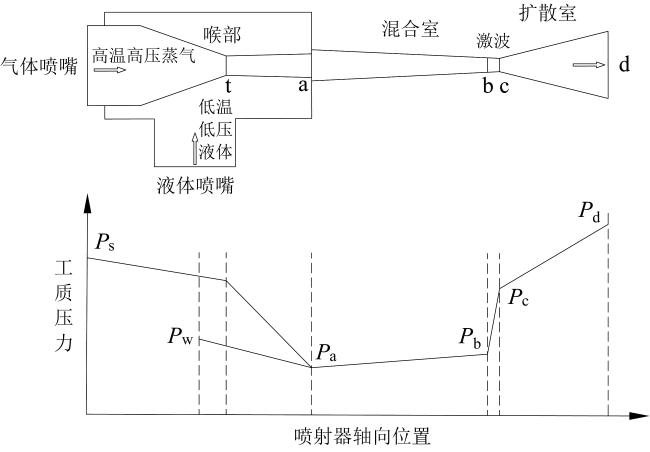
Fig. 1 Schematic diagram of vapor-liquid injector图1 气液喷射器结构示意图 |
图2所示为IORC的循环工作过程,一定压力的工质初蒸气进入膨胀机做功至抽气压力(5—6),在这一抽气压力下,一部分工质作为工作流体进入气液喷射器,经过超音速气体喷嘴后形成超音速射流。剩余工质则继续在膨胀机中膨胀(6—7),经过冷凝器冷凝成过冷液后(7—8—9—1),在蒸气的引射作用下进入气液喷射器,在其中两股流体直接接触后升压,得到蒸发压力下的过冷液态工质(6&1—2),随后,液态工质进入蒸发器在其中被热水加热重新形成初蒸气(2—3—4—5),完成循环。
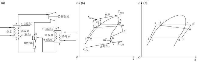
Fig. 2 Schematic diagram of IORC: (a) system diagram; (b) T-s diagram; (c) P-h diagram图2 IORC流程图:(a)系统图;(b)温-熵图;(c)压-焓图 |
图3所示为BORC的循环工作过程,一定压力的工质初蒸气进入膨胀机做功至出口(5—6),经过冷凝器冷凝成过冷液后(6—7—8—1),进入工质泵加压,得到蒸发压力下的过冷液态工质(1—2),随后,液态工质进入蒸发器在其中被热水加热重新形成初蒸气(2—3—4—5),完成循环。
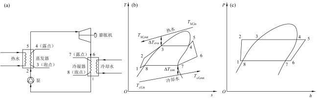
Fig. 3 Schematic diagram of BORC: (a) system diagram; (b) T-s diagram; (c) P-h diagram图3 BORC流程图:(a)系统图;(b)温-熵图;(c)压-焓图 |
2 数学物理模型
2.1 假设
2.2 气液喷射器模型
基于文献[21],建立气液喷射器的一维模型。
2.2.1 气体喷嘴
气体喷嘴入口至喉部为渐缩布局,气态工质从入口开始膨胀,将自身焓值转化为动能,在出口达到超音速:
${{u}_{\text{as}}}=\sqrt{2{{\eta }_{\text{vnoz}}}\left( {{h}_{\text{s}}}-{{h}_{\text{as,is}}} \right)}$ (1)
${{\eta }_{\text{vnoz}}}=\frac{{{h}_{\text{s}}}-{{h}_{\text{as}}}}{{{h}_{\text{s}}}-{{h}_{\text{as,is}}}}$ (2)
${{h}_{\text{as,is}}}=h\left( {{P}_{\text{as}}},{{s}_{\text{s}}} \right)$ (3)
${{\rho }_{\text{as}}}=\rho \left( {{P}_{\text{as}}},{{h}_{\text{as}}} \right)$ (4)
${{A}_{\text{as}}}=\frac{{{m}_{\text{s}}}}{{{\rho }_{\text{as}}}\ \ {{u}_{\text{as}}}}$ (5)
2.2.2 液体喷嘴
根据CHEN等[21]的假设,液体喷嘴出口的压力为液体喷嘴入口温度下的饱和压力:
${{P}_{\text{aw}}}={{P}_{\text{sat}}}\left( {{T}_{\text{w}}} \right)$ (6)
忽略液态工质在液体喷嘴进出口的密度变化:
(7)
${{h}_{\text{aw}}}={{h}_{\text{w}}}-\frac{1}{2}u_{\text{aw}}^{\text{2}}$ (8)
${{A}_{\text{aw}}}=\frac{{{m}_{\text{w}}}}{{{\rho }_{\text{w}}}{{u}_{\text{aw}}}}$ (9)
2.2.3 混合室
在混合室中,超音速气态工质与过冷的液态工质直接接触,发生质量、动量、热量的交换。
混合室入口工质的质量流量为:
${{m}_{\text{b}}}={{m}_{\text{s}}}+{{m}_{\text{w}}}$ (10)
质量守恒:
${{u}_{\text{b}}}=\frac{{{m}_{\text{b}}}}{{{\rho }_{\text{b}}}{{A}_{\text{b}}}}$ (11)
动量守恒:
${{P}_{\text{b}}}{{A}_{\text{b}}}+{{m}_{\text{b}}}{{u}_{\text{b}}}+F={{P}_{\text{as}}}{{A}_{\text{as}}}+{{P}_{\text{aw}}}{{A}_{\text{aw}}}+{{m}_{\text{s}}}{{u}_{\text{as}}}+{{m}_{\text{w}}}{{u}_{\text{aw}}}$ (12)
其中:
$F=\varphi {{P}_{\text{aw}}}\left( {{A}_{\text{as}}}+{{A}_{\text{aw}}}-{{A}_{\text{b}}} \right)$ (13)
能量守恒:
${{m}_{\text{b}}}\left( {{h}_{\text{b}}}+\frac{1}{2}u_{\text{b}}^{\text{2}} \right)={{m}_{\text{s}}}\left( {{h}_{\text{as}}}+\frac{1}{2}u_{\text{as}}^{\text{2}} \right)+{{m}_{\text{w}}}\left( {{h}_{\text{aw}}}+\frac{1}{2}u_{\text{aw}}^{\text{2}} \right)$ (14)
式中:F为沿混合室入口延伸至激波前段的壁面阻力;φ为一个与混合室结构、粗糙度以及运行工况有关的系数,根据CHEN等[21]的建议,取1.2。
2.2.4 激波
质量守恒:
${{\rho }_{\text{c}}}{{u}_{\text{c}}}={{\rho }_{\text{b}}}{{u}_{\text{b}}}$ (15)
动量守恒:
${{P}_{\text{c}}}+{{\rho }_{\text{c}}}u_{\text{c}}^{\text{2}}={{P}_{\text{b}}}+{{\rho }_{\text{b}}}u_{\text{b}}^{\text{2}}$ (16)
能量守恒:
${{\rho }_{\text{c}}}{{u}_{\text{c}}}\left( {{h}_{\text{c}}}+\frac{1}{2}u_{\text{c}}^{\text{2}} \right)={{\rho }_{\text{b}}}{{u}_{\text{b}}}\left( {{h}_{\text{b}}}+\frac{1}{2}u_{\text{b}}^{\text{2}} \right)$ (17)
2.2.5 扩散室
升压后的过冷液在扩散室内进一步将动能转化为压升:
${{P}_{\text{d}}}={{P}_{\text{c}}}+\frac{1}{2}{{\eta }_{\text{dif}}}{{\rho }_{\text{c}}}u_{\text{c}}^{\text{2}}$ (18)
2.2.6 无量纲量
引射系数为低温低压液体(第二流体)质量流量与高温高压蒸气(第一流体)质量流量的比值:
$U=\frac{{{m}_{\text{w}}}}{{{m}_{\text{s}}}}$ (19)
喷射器面积比为混合室末端的横截面积与气体喷嘴喉部面积的比值:
$Ar=\frac{{{A}_{\text{b}}}}{{{A}_{\text{ts}}}}$ (20)
喷射器升压比为喷射器出口工质压力与入口蒸气压力的比值:
$Pl=\frac{{{P}_{\text{d}}}}{{{P}_{\text{s}}}}$ (21)
喷射器㶲效率反映了对高温高压第一流体的可用能利用程度,定义为[25]:
${{\eta }_{\text{inj}}}=U\frac{\left( {{h}_{\text{d}}}-{{h}_{\text{w}}} \right)-{{T}_{\text{0}}}\left( {{s}_{\text{d}}}-{{s}_{\text{w}}} \right)}{\left( {{h}_{\text{s}}}-{{h}_{\text{d}}} \right)-{{T}_{\text{0}}}\left( {{s}_{\text{s}}}-{{s}_{\text{d}}} \right)}\times 100%$ (22)
2.3 系统模型
系统的热力模型见表1。
Table 1 Thermodynamic model of system表1 循环热力模型 |
| 循环 | 部件 | 模型 |
|---|---|---|
| IORC | 蒸发器 | ${{Q}_{\text{eva}}}={{m}_{\text{wf}}}\left( {{h}_{\text{5}}}-{{h}_{\text{2}}} \right)$ |
| 膨胀机 | $\begin{aligned}W_{\exp } & =W_{\exp , 5-6}+W_{\exp , 6-7} \\& =\eta_{\exp } m_{\mathrm{wf}}\left\{\begin{array}{l}\left(h_5-h_{6, \text { is }}\right)+ \\{[U /(1+U)]\left(h_6-h_{7, \text { is }}\right)}\end{array}\right\}\end{aligned}$ | |
| 冷凝器 | ${{Q}_{\text{con}}}=\left[ {U}/{\left( 1+U \right)}\; \right]{{m}_{\text{wf}}}\left( {{h}_{7}}-{{h}_{1}} \right)$ | |
| 喷射器 | ${{h}_{6}}+U{{h}_{1}}=\left( 1+U \right){{h}_{2}}$ | |
| 净输出功 | ${{W}_{\text{net}}}={{W}_{\text{exp}}}$ | |
| BORC | 蒸发器 | ${{Q}_{\text{eva}}}={{m}_{\text{wf}}}\left( {{h}_{\text{5}}}-{{h}_{\text{2}}} \right)$ |
| 膨胀机 | ${{W}_{\text{exp}}}={{\eta }_{\text{exp}}}{{m}_{\text{wf}}}\left( {{h}_{\text{5}}}-{{h}_{\text{6,is}}} \right)$ | |
| 冷凝器 | ${{Q}_{\text{con}}}={{m}_{\text{wf}}}\left( {{h}_{\text{6}}}-{{h}_{\text{1}}} \right)$ | |
| 工质泵 | ${{W}_{\text{pu}}}={{{m}_{\text{wf}}}\left( {{h}_{\text{2,is}}}-{{h}_{\text{1}}} \right)}/{{{\eta }_{\text{pu}}}}\;$ | |
| 净输出功 | ${{W}_{\text{net}}}={{W}_{\text{exp}}}-{{W}_{\text{pu}}}$ |
蒸发器或冷凝器的换热面积为:
${{A}_{\text{eva/con}}}=\frac{{{Q}_{\text{sub}}}}{{{K}_{\text{sub}}}\ \ \Delta {{T}_{\text{sub}}}}+\frac{{{Q}_{\text{two}}}}{{{K}_{\text{two}}}\ \ \Delta {{T}_{\text{two}}}}+\frac{{{Q}_{\text{sup}}}}{{{K}_{\text{sup}}}\ \ \Delta {{T}_{\text{sup}}}}$ (23)
换热器总面积为:
${{A}_{\text{tot}}}={{A}_{\text{eva}}}+{{A}_{\text{con}}}$ (24)
式中:ΔT为两种流体之间的对数平均温差;总传热系数K表示如下:
$K=\frac{1}{\ \frac{1}{k_{\mathrm{wf}}}\ +\ \frac{1}{k_{\mathrm{hfccf}}}\ +\ \frac{\delta}{\lambda}\ }$ (25)
单位净输出功所需换热器面积(specific heat transfer area, ASHT)可被用于评估循环中换热器的经济性[29],表达式为:
${{A}_{\text{SHT}}}\text{=}\frac{{{A}_{\text{tot}}}}{{{W}_{\text{net}}}}$ (26)
3 模型验证
由于IORC仍处于理论研究阶段,因此没有相关的实验数据来验证该模型。然而,IORC可以被视为用气液喷射器取代BORC的工质泵。因此,下面分别对BORC模型和气液喷射器模型进行验证,这在一定程度上可以被视为对IORC模型的验证。
3.1 BORC模型验证
Table 2 Model validation of BORC表2 BORC模型的验证 |
| 工质 | 热效率/% | 相对误差/% | |
|---|---|---|---|
| 文献[30] | 本文模型 | ||
| R600 | 10.151 | 10.147 | 0.039 |
| R600a | 9.899 | 9.887 | 0.121 |
| R601 | 10.372 | 10.378 | 0.058 |
| R601a | 10.282 | 10.281 | 0.010 |
3.2 气液喷射器模型验证
Table 3 Model validation of vapor-liquid injector表3 气液喷射器模型验证 |
| 气体喷嘴入口压力/MPa | 气体喷嘴出口压力/MPa | 混合室出口压力/MPa | 扩散室出口压力/MPa | ||||||||
|---|---|---|---|---|---|---|---|---|---|---|---|
| 文献[31] | 本文模型 | 相对误差/% | 文献[31] | 本文模型 | 相对误差/% | 文献[31] | 本文模型 | 相对误差/% | |||
| 0.200 | 0.049 | 0.049 | 0.227 | 0.340 | 0.334 | 1.732 | 0.399 | 0.388 | 2.810 | ||
| 0.300 | 0.069 | 0.073 | 6.163 | 0.478 | 0.506 | 5.839 | 0.550 | 0.555 | 1.014 | ||
| 0.400 | 0.098 | 0.097 | 1.659 | 0.659 | 0.674 | 2.409 | 0.708 | 0.720 | 1.657 | ||
| 0.500 | 0.119 | 0.120 | 0.457 | 0.799 | 0.844 | 5.607 | 0.849 | 0.885 | 4.239 | ||
| 0.600 | 0.136 | 0.143 | 5.202 | 0.908 | 1.015 | 11.752 | 0.948 | 1.050 | 10.824 | ||
4 结果与讨论
4.1 IORC特性分析
本节对IORC的运行特性开展分析,探究喷射器引射系数U、喷射器面积比Ar、冷凝器出口过冷度Tsub对循环的喷射器升压比Pl、喷射器㶲效率ηinj、净输出功Wnet、单位净输出功所需换热器面积ASHT的影响,循环运行参数如表4所示。需要指出的是,特性分析时,一个参数发生变化,其他参数保持不变。
Table 4 Operation parameters of cycle表4 循环运行参数 |
| 参数 | 取值 | 变化范围 |
|---|---|---|
| 热水入口温度Thf,in | 140 ℃ | — |
| 热水温降ΔThf | 40 ℃ | — |
| 热水压力Phf | 1.0 MPa | — |
| 热水流量mhf | 1 kg/s | — |
| 冷却水入口温度Tcf,in | 20 ℃ | — |
| 冷却水压力Pcf | 0.20 MPa | — |
| 蒸发器出口过热度Tsup | 5 ℃ | — |
| 冷凝器出口过冷度Tsub | 5 ℃ | 3 ~ 20 ℃ |
| 冷凝温度Tcon | 45 ℃ | — |
| 喷射器面积比Ar | 0.60 | 0.30 ~ 0.80 |
| 喷射器引射系数U | 2.50 | 2.00 ~ 3.30 |
| 蒸发器夹点温差ΔTeva | 5 ℃ | — |
| 冷凝器夹点温差ΔTcon | 5 ℃ | — |
| 膨胀机等熵效率ηexp | 70% | — |
4.1.1 喷射器引射系数的影响
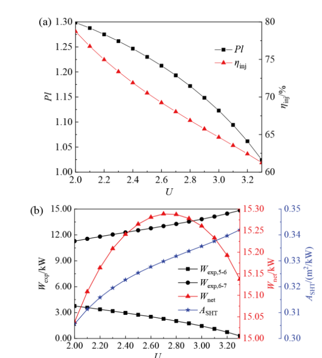
Fig. 4 Effect of entrainment ratio of the injector on IORC performance: (a) pressure lift of the injector and exergy efficiency of the injector; (b) expander output power, net power and specific heat transfer area图4 喷射器引射系数对IORC性能的影响:(a)喷射器升压比和喷射器㶲效率;(b)膨胀机输出功、净输出功和单位净输出功所需换热器面积 |
图4(b)所示为U对Wnet、ASHT的影响。在U的增加过程中,Pl减小,这意味着5—6过程的焓差(h5 - h6)减小,6—7过程的焓差(h6 - h7)增加,使得5—6过程的膨胀机输出功Wexp,5-6减小,6—7过程的膨胀机输出功Wexp,6-7增加。Wexp,5-6和Wexp,6-7相反的变化趋势使得Wnet在U增加的过程中呈现先增加后减小的趋势,当U = 2.70时,Wnet有最大值15.289 kW,这说明存在一个最佳的U使得IORC的Wnet达到最大。在U增加的过程中,根据喷射器进出口的能量守恒,hd(即蒸发器入口焓值h2)将降低,然而,由于热水流量mhf、入口温度Thf,in、热水温降ΔThf和蒸发器夹点温差ΔTeva是固定的,如果蒸发温度Teva保持不变,工质流体在过冷段吸收的热量Q2-3将与该段热水释放的热量不一致。因此为了满足能量平衡,Teva将升高,使得蒸发器中热水和工质的平均传热温差减小,蒸发器换热面积Atot,eva增加,ASHT增加。
4.1.2 喷射器面积比的影响
图5(a)所示为Ar对Pl、ηinj的影响。可以看出,随着Ar的增加,Pl下降。这是由于Ar的增加意味着混合室末端的横截面积Ab增大。根据式(11),这将导致注射器混合室出口处的速度和动能降低,Pl从而降低,根据式(21),这意味着喷射器出口过冷液的压力Pd降低,同时喷射器入口第一流体的压力Ps(汽轮机抽气压力P6)升高。而Ps(P6)的升高意味着喷射器入口第一流体的温度Ts(T6)升高,根据能量平衡,喷射器出口过冷液的温度Td也升高。因此在Ar的增加过程中,喷射器出口Pd的降低和Td的升高导致喷射器出口工质的比熵sd增大,根据式(22),这使得第二流体得到的可用能减少而第一流体付出的可用能增加,因此ηinj减小。这与CHEN等[18]和LI等[25]的结果相吻合。
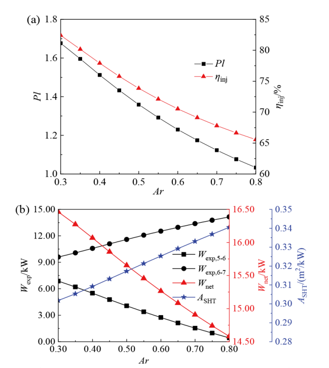
Fig. 5 Effect of area ratio of the injector on IORC performance: (a) pressure lift of the injector and exergy efficiency of the injector; (b) expander output power, net power and specific heat transfer area图5 喷射器面积比对IORC性能的影响:(a)喷射器升压比和喷射器㶲效率;(b)膨胀机输出功、净输出功和单位净输出功所需换热器面积 |
图5(b)所示为Ar对Wnet、ASHT的影响。由于Pl在Ar增加的过程中下降,这会导致Wexp,5-6减小而Wexp,6-7增加,但是Wexp,5-6减小占主导,因此Wnet减小,ASHT则增加。
4.1.3 冷凝器出口过冷度的影响
图6(a)所示为Tsub对Pl、ηinj的影响。可以看出,随着Tsub的升高,Pl增加。这主要是由于Tsub的增加会使喷射器入口处第二流体的温度Tw降低,使得液体喷嘴出口(混合室入口)的压力Paw减小,根据式(13),混合室的壁面阻力F也减小,因此Pl增加。Tsub的升高还会使喷射器入口处的第一流体和第二流体之间的温差增大,换热过程的不可逆损失也增大,因此ηinj减小。
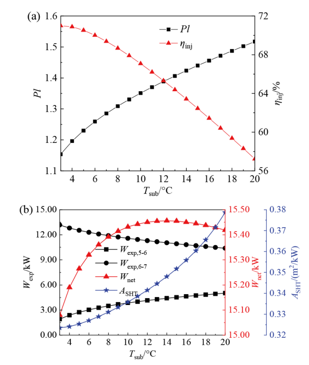
Fig. 6 Effect of subcooling of the condenser outlet on IORC performance: (a) pressure lift of the injector and exergy efficiency of the injector; (b) expander output power, net power and specific heat transfer area图6 冷凝器出口过冷度对IORC性能的影响:(a)喷射器升压比和喷射器㶲效率;(b)膨胀机输出功、净输出功和单位净输出功所需换热器面积 |
图6(b)所示为Tsub对Wnet、ASHT的影响。在Tsub升高的过程中,Pl增加,这意味着(h5-h6)增加,(h6-h7)减小,使得Wexp,5-6增加,Wexp,6-7减小。Wexp,5-6和Wexp,6-7相反的变化趋势使得Wnet在Tsub增加的过程中呈现先增加后减小的趋势,当Tsub = 14 ℃时,Wnet达到最大值15.456 kW,说明存在一个最佳的Tsub使得IORC的Wnet达到最大。在Tsub升高的过程中,根据喷射器进出口的能量守恒,hd将降低,与4.1.1节同理,Teva将升高,使得蒸发器中热水和工质的平均传热温差减小,蒸发器换热面积Atot,eva增加。此外,Tsub的升高还会使冷凝器中工质和冷却水的平均传热温差减小,冷凝器换热面积Atot,con增加。因此总换热器面积Atot增加,ASHT则增加。
4.2 循环性能对比
5 结论
构建气液喷射升压有机朗肯循环(IORC),以气液喷射器取代传统的工质泵作为升压设备,在验证模型的准确性后,对IORC开展了运行特性分析,并与基本有机朗肯循环(BORC)进行了对比,得到以下结论:
(1)增加喷射器引射系数会使IORC的喷射器升压比和喷射器㶲效率降低,单位净输出功所需换热器面积增加。存在一个最佳引射系数2.70,使得净输出功有最大值。
(2)增加喷射器面积比会使得IORC的喷射器升压比、喷射器㶲效率以及净输出功降低,单位净输出功所需换热器面积略微增加。
(3)增加冷凝器出口过冷度会增加IORC的喷射器升压比和单位净输出功所需换热器面积,降低喷射器㶲效率。存在一个最佳过冷度14 ℃,使得净输出功有最大值。
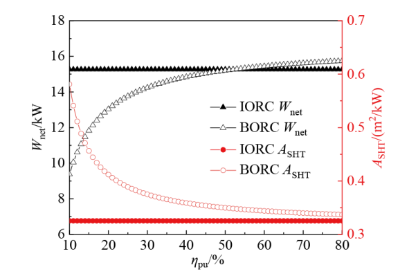
(4)IORC比BORC具有更好的换热器经济性。当工质泵效率低于52%时,IORC净输出功相比BORC更具有优势,对于小型有机朗肯循环机组,IORC有相当可观的应用潜力。
符号表:
A 面积,m2
ASHT 单位净输出功所需换热器面积,m2/kW
Ar 喷射器面积比
F 喷射器混合室壁面阻力,N
h 比焓,kJ/kg
K 总传热系数,kW/(m2∙℃)
k 流体对流传热系数,kW/(m2∙℃)
m 质量流量,kg/s
P 压力,Pa
Q 吸热量,kW
s 比熵,kJ/(kg∙K)
T 温度,℃
ΔT 温差,℃
U 引射系数
u 速度,m/s
W 功,kW
φ 喷射器系数
λ 导热系数,kW/(m∙℃)
δ 传热板壁厚,m
ρ 密度,kg/m3
η 效率
下角标:
0 环境
wf 工质
hf 热水
cf 冷却水
dif 扩散室
eva 蒸发器
con 冷凝器
exp 膨胀机
in 入口
is 等熵过程
inj 喷射器
lnoz 液体喷嘴
net 净
out 出口
pu 工质泵
sat 饱和
sub 过冷
sup 过热
tot 总
two 两相
vnoz 气体喷嘴
s 气态
w 液态
t 气体喷嘴喉部
a, b, c, d 图1喷射器的位置