 PDF(4796 KB)

Preparation and Electrochemical Properties of a Lithium-Rich Layered Material with Highly Exposed {010} Crystallographic Planes
PAN Yu-long, ZHANG Gai-ge, TANG Guang-xia, LI Rong-dong, GUO Ruo-yu, CHEN Min
Advances in New and Renewable Energy ›› 2023, Vol. 11 ›› Issue (2) : 181-188.
PDF(4796 KB)
 PDF(4796 KB)
Preparation and Electrochemical Properties of a Lithium-Rich Layered Material with Highly Exposed {010} Crystallographic Planes
 ({{custom_author.role_en}}), {{javascript:window.custom_author_en_index++;}}
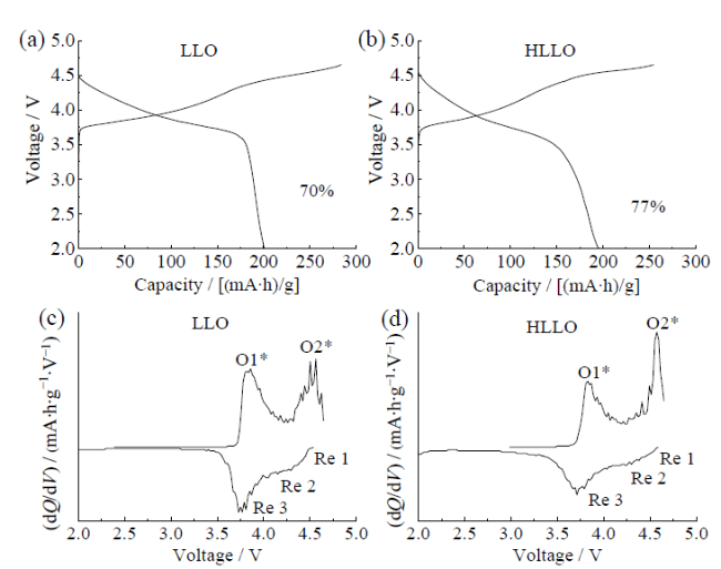
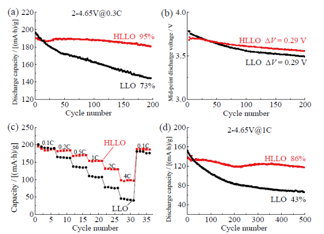
The layered lithium-rich oxide has a specific capacity of more than 250 mA∙h/g, which make it one of the most promising cathodes for the high energy density lithium-ion batteries. However, the problems of low initial Coulombic efficiency, poor cycle, and rate performance limit its practical application. Here, a lithium-rich layered oxide Li1.17Ni0.4Co0.05Mn0.38O2 (HLLO) with highly exposed {010} crystallographic plane was synthesized by a precursor-template conversion and solid phase reaction method. The structural characterizations of X-ray diffractometer (XRD), scanning electron microscopy (SEM), and transmission electron microscopy (TEM) demonstrated that the exposed {010} crystallographic plane of HLLO was obvious. The electrochemical performance showed that such planes could accelerate lithium ions’ diffusion, and lithium ions’ diffusion coefficient was increased from 9.5×10⁻¹⁴ cm2/s to 3.9×10⁻¹³ cm2/s. Compared with the traditional Li1.17Ni0.4Co0.05Mn0.38O2 (LLO), the initial Coulombic efficiency of HLLO increased from 70% to 77% at 0.1 C, and its capacity retention rate increased from 43% to 86% at 1 C after 500 cycles.
lithium-ion battery / Li-rich layered cathode material / {010} crystallographic plane {{custom_keyword}} /
Table 1 Composition analysis of LLO and HLLO materials by ICP表1 ICP分析LLO和HLLO材料的成分 |
| Sample | Content / % | |||
|---|---|---|---|---|
| Li | Mn | Ni | Co | |
| LLO | 1.169 | 0.381 | 0.412 | 0.051 |
| HLLO | 1.171 | 0.379 | 0.401 | 0.049 |
Table 2 The data of cycling performance for the LLO and HLLO samples at 0.3 C and 1 C rate (2.0 - 4.65 V)表2 LLO和HLLO样品在0.3 C和1 C下的循环性能数据(2.0 ~ 4.65 V) |
| Sample | Condition | Specific capacity / (mA∙h/g) | Capacity retention / % |
|---|---|---|---|
| LLO | 0.3 C, 1st | 197 | 73 |
| 0.3 C, 200 th | 144 | ||
| 1.0 C, 1 st | 152 | 43 | |
| 1.0 C, 500 th | 66 | ||
| HLLO | 0.3 C, 1 st | 190 | 95 |
| 0.3 C, 200 th | 181 | ||
| 1.0 C, 1 st | 137 | 86 | |
| 1.0 C, 500 th | 117 |
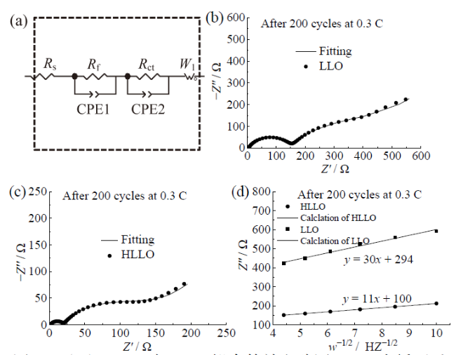
Fig. 8 (a) Fitted equivalent circuit diagram of HLLO and LLO; electrochemical impedance spectra of LLO (b) and HLLO (c) after 200 cycles; (d) the curve comparison of the real impedance Z″ versus ω-1/2 and corresponding linear fitting图8 (a)HLLO与LLO拟合等效电路图;200次循环后LLO(b)和HLLO(c)材料的交流阻抗谱;(d)实部阻抗Z″ 与ω-1/2的曲线比较 |
Table 3 Fitting parameters for electrochemical spectra of LLO and HLLO after 200 cycles表3 LLO和HLLO样品在循环200圈后阻抗测试的拟合结果 |
| Sample | Rs / Ω | Rf / Ω | Rct / Ω | DLi+ / (cm2/s) |
|---|---|---|---|---|
| LLO | 2.4 | 112.6 | 350.3 | 9.5×10⁻¹⁴ |
| HLLO | 2.1 | 17.3 | 100.2 | 3.9×10⁻¹³ |
| [1] |
{{custom_citation.content}}
{{custom_citation.annotation}}
|
| [2] |
{{custom_citation.content}}
{{custom_citation.annotation}}
|
| [3] |
{{custom_citation.content}}
{{custom_citation.annotation}}
|
| [4] |
{{custom_citation.content}}
{{custom_citation.annotation}}
|
| [5] |
{{custom_citation.content}}
{{custom_citation.annotation}}
|
| [6] |
{{custom_citation.content}}
{{custom_citation.annotation}}
|
| [7] |
{{custom_citation.content}}
{{custom_citation.annotation}}
|
| [8] |
{{custom_citation.content}}
{{custom_citation.annotation}}
|
| [9] |
{{custom_citation.content}}
{{custom_citation.annotation}}
|
| [10] |
{{custom_citation.content}}
{{custom_citation.annotation}}
|
| [11] |
{{custom_citation.content}}
{{custom_citation.annotation}}
|
| [12] |
{{custom_citation.content}}
{{custom_citation.annotation}}
|
| [13] |
{{custom_citation.content}}
{{custom_citation.annotation}}
|
| [14] |
{{custom_citation.content}}
{{custom_citation.annotation}}
|
| [15] |
{{custom_citation.content}}
{{custom_citation.annotation}}
|
| [16] |
{{custom_citation.content}}
{{custom_citation.annotation}}
|
| [17] |
{{custom_citation.content}}
{{custom_citation.annotation}}
|
| [18] |
{{custom_citation.content}}
{{custom_citation.annotation}}
|
| [19] |
{{custom_citation.content}}
{{custom_citation.annotation}}
|
| [20] |
{{custom_citation.content}}
{{custom_citation.annotation}}
|
| [21] |
{{custom_citation.content}}
{{custom_citation.annotation}}
|
| [22] |
{{custom_citation.content}}
{{custom_citation.annotation}}
|
| [23] |
{{custom_citation.content}}
{{custom_citation.annotation}}
|
| [24] |
{{custom_citation.content}}
{{custom_citation.annotation}}
|
| [25] |
{{custom_citation.content}}
{{custom_citation.annotation}}
|
| [26] |
{{custom_citation.content}}
{{custom_citation.annotation}}
|
| [27] |
{{custom_citation.content}}
{{custom_citation.annotation}}
|
| [28] |
{{custom_citation.content}}
{{custom_citation.annotation}}
|
| [29] |
{{custom_citation.content}}
{{custom_citation.annotation}}
|
| [30] |
{{custom_citation.content}}
{{custom_citation.annotation}}
|
| [31] |
{{custom_citation.content}}
{{custom_citation.annotation}}
|
| [32] |
{{custom_citation.content}}
{{custom_citation.annotation}}
|
| [33] |
{{custom_citation.content}}
{{custom_citation.annotation}}
|
| {{custom_ref.label}} |
{{custom_citation.content}}
{{custom_citation.annotation}}
|


 PDF(4796 KB)
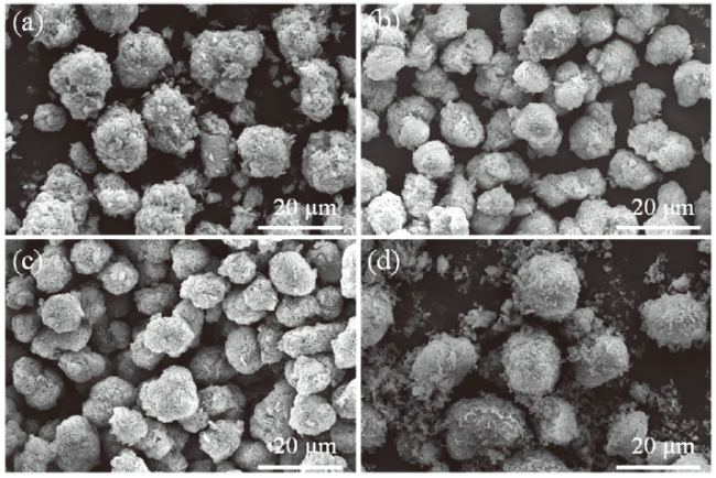
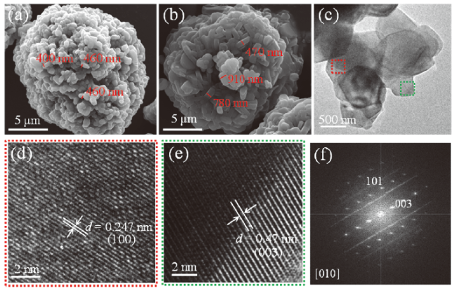
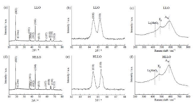
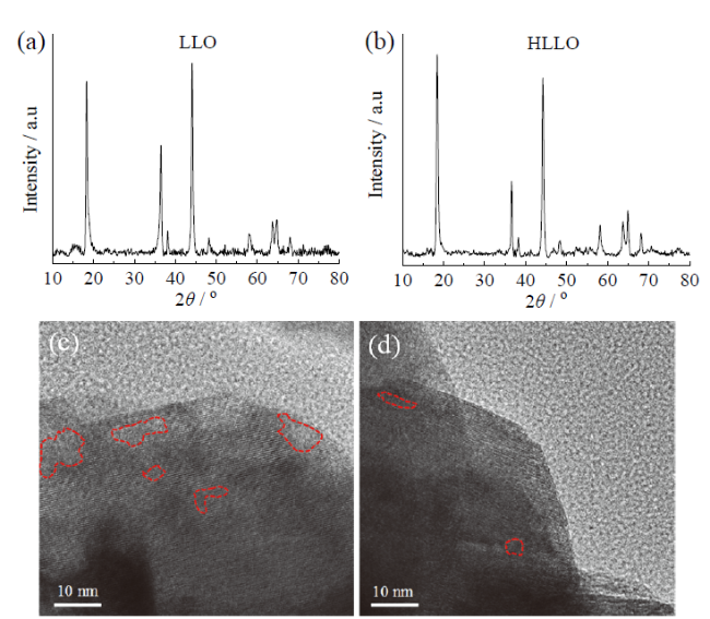
 Fig. 1 SEM images of precursors with different reaction times: (a) 3 h; (b) 6 h; (c) 9 h; (d) 12 hFig. 2 (a) SEM image of LLO; SEM image (b), TEM image (c), top (bottom) plane HRTEM image (d), side HRTEM image (e) and FFT image (f) of HLLOFig. 3 XRD spectrum (a, b) and Raman spectrum (c) of LLO; XRD spectrum (d, e) and Raman spectrum (f) of HLLO
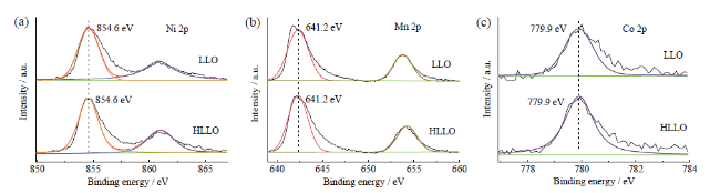
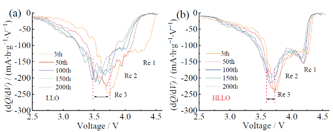
 Table 1 Composition analysis of LLO and HLLO materials by ICPFig. 4 XPS spectra of the LLO and HLLO samples: (a) Ni 2p; (b) Mn 2p; (c) Co 2pFig. 5 Typical initial charge-discharge curves of LLO (a) and HLLO (b) at 0.1 C; dQ/dV profiles of LLO (c) and HLLO (d)Fig. 6 (a) Cycle performance of LLO and HLLO after 200 cycles at 0.3 C; (b) median voltage change curve during cycling; (c) rate performance; (d) cycle performance of 500 cycles at 1 CTable 2 The data of cycling performance for the LLO and HLLO samples at 0.3 C and 1 C rate (2.0 - 4.65 V)Fig. 7 dQ/dV profiles of LLO (a) and HLLO (b) for different cycles at 0.3 CFig. 8 (a) Fitted equivalent circuit diagram of HLLO and LLO; electrochemical impedance spectra of LLO (b) and HLLO (c) after 200 cycles; (d) the curve comparison of the real impedance Z″ versus ω-1/2 and corresponding linear fittingTable 3 Fitting parameters for electrochemical spectra of LLO and HLLO after 200 cyclesFig. 9 XRD patterns of LLO (a) and HLLO (b), HRTEM patterns of LLO (c) and HLLO (d) after 200 cycles at 0.3 C
/
| 〈 |
|
〉 |


